Element substrate, liquid discharge head, and printing apparatus
a liquid discharge head and element substrate technology, applied in printing and other directions, can solve the problems of affecting the wettability of the nozzle surface, the failure of the discharge head in some or all of the nozzles, and the factoring of cost increases, so as to achieve the effect of reducing the cost configuration
- Summary
- Abstract
- Description
- Claims
- Application Information
AI Technical Summary
Benefits of technology
Problems solved by technology
Method used
Image
Examples
first embodiment
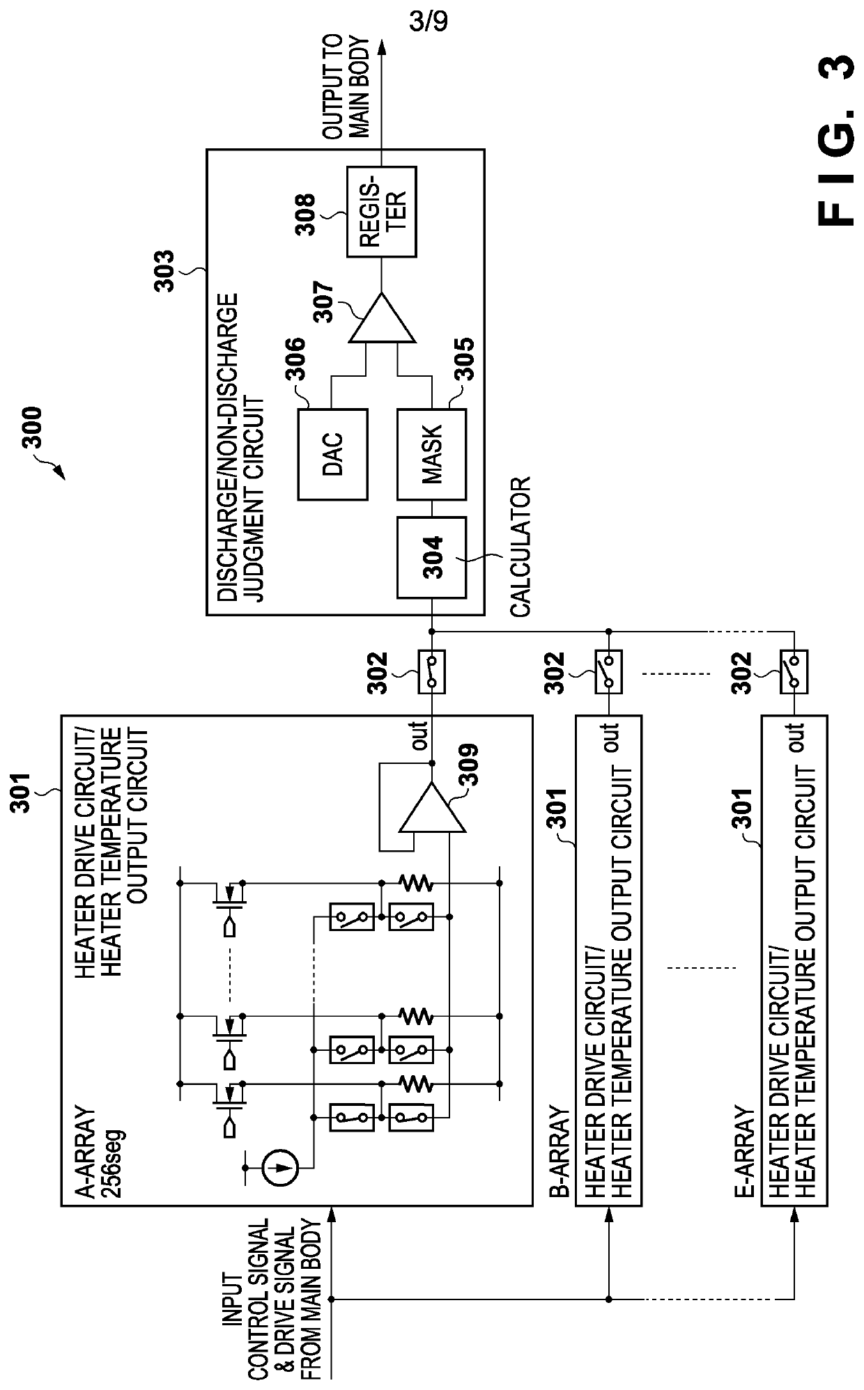
[0058]FIG. 4 is an equivalent circuit diagram illustrating a detailed configuration of the heater driving / heater temperature output circuit 301 according to the first embodiment.
[0059]FIG. 5 is a timing chart for a signal according to a heater temperature detection of the heater driving / heater temperature output circuit 301 illustrated in FIG. 4.
[0060]According to FIG. 4, 256 drivers D1 to D256 for driving 256 heaters H1 to H256 are in an NDMOS source-follower configuration, and the heaters H1 to H256 are series-connected to the drivers D1 to D256. A power supply voltage supplied in a parallel connection to the 256 drivers D1 to D256 are of a voltage of about 24V to 34V, and the drivers D1 to D256 have a source-drain tolerable voltage that adequately satisfies this voltage. In the source-follower configuration, the source voltage (the voltage on the+side of the heaters H1 to H256) follows the gate voltage, and a voltage that is lower by Vth+(2Id / β)1 / 2 than the gate voltage is output...
second embodiment
[0068]An example of a heater temperature detection, that is different from the first embodiment, that uses the heater driving / heater temperature output circuit 301 illustrated in the first embodiment will be described.
[0069]FIG. 6 and FIG. 7 are timing charts for signals according to the heater temperature detection by the heater driving / heater temperature output circuit 301, according to the second embodiment. Note that in FIG. 6 and FIG. 7, the description regarding details of these signals is omitted since the same signals as those mentioned in FIG. 5 are used.
[0070]According to FIG. 5, in the first embodiment, the wave height values (current values) of the heater currents that flow in the main pulse 220 and the post pulse 221 are the same, and the pulse width of the post pulse 221 is shorter than the pulse width of the main pulse 220. In contrast to this, here, as illustrated in FIG. 6, the current values of a main pulse 401 and a post pulse 402 are different, and the current va...
third embodiment
[0076]FIG. 8 is an equivalent circuit diagram that illustrates a detailed configuration of the heater driving / heater temperature output circuit 301 according to the third embodiment. Note that in FIG. 8, the same reference numerals and reference symbols are added to components and signals that are the same as those already described with reference to FIG. 4, and description thereof will be omitted.
[0077]As can be seen by comparing FIG. 8 and FIG. 4, in the example illustrated in FIG. 4, the source-follower configuration drivers D1 to D256 are arranged on the power source voltage VH side, but in the exampled illustrated in FIG. 8, PMOSs 203 of a source-follower configuration are arranged on the ground voltage GNDH side. Also, the control voltage VCNTL is applied to the gate of the PMOSs, and the drain voltage is controlled to a voltage where (2Id / β)1 / 2 is added onto the control voltage VCNTL at the time of driving the heater. Accordingly, in the configuration illustrated in FIG. 8, e...
PUM
 Abstract
Description
Claims
Application Information
 - R&D
- Intellectual Property
- Life Sciences
- Materials
- Tech Scout
- Unparalleled Data Quality
- Higher Quality Content
- 60% Fewer Hallucinations
Browse by: Latest US Patents, China's latest patents, Technical Efficacy Thesaurus, Application Domain, Technology Topic, Popular Technical Reports.
© 2025 PatSnap. All rights reserved.Legal|Privacy policy|Modern Slavery Act Transparency Statement|Sitemap|About US| Contact US: help@patsnap.com


