Gas-liquid dissolving apparatus

a technology of gas-liquid dissolving apparatus and gas-liquid dissolving liquid, which is applied in the direction of dissolving, combustible gas purification/modification, machines/engines, etc., can solve the problems of water pollution, benthoses often becoming extinct, and oxygen deficiency of the bottom layer, so as to improve the contact area and the contact opportunity, and efficiently increase the oxygen concentration of the oxygen-deficient water area. , to prevent the bubbles from

Active Publication Date: 2009-08-11
MATSUE DOKEN +1
View PDF32 Cites 9 Cited by
  • Summary
  • Abstract
  • Description
  • Claims
  • Application Information

AI Technical Summary

Benefits of technology

[0045]The gas-liquid dissolving apparatus according to the present invention can increase the contact area and the contact opportunity between the gas and the water by the force of the gas-liquid multi-phase fluid ejected from the nozzle in a superimposed manner, and accelerate the dissolution of the gas into the water. It is, therefore, possible to efficiently increase the oxygen concentration of the oxygen-deficient water area. In addition, the gas-liquid dissolving apparatus according to the present invention traps the water stream by the wall of the gas-liquid dissolving chamber, separates fine bubbles in the gas-liquid separating chamber, and continuously takes out only the high dissolved oxygen concentration water. It is, therefore, possible to prevent the bubbles from curling up the bottom materials. The sealed reaction container such as the high pressure tank and the equipment for controlling the internal pressure and the water level of the reaction container are unnecessary. Therefore, the apparatus itself can be simplified, and the gas-liquid dissolving apparatus can be provided at low cost.
[0046]The present invention provides a gas-liquid dissolving apparatus that causes the gas-liquid multi-phase fluid ejected from the nozzle to flow along the dome without stagnation, thereby efficiently increasing the contact opportunity between the gas and the water, efficiently increasing the contact area therebetween, and further accelerating the dissolution of the gas into the water. Thus, it is possible to provide the gas-liquid dissolving apparatus that can more efficiently increase the oxygen concentration of the oxygen-deficient water area.
[0047]The present invention provides the gas-liquid dissolving apparatus that urges the gas-liquid multi-phase fluid to flow into the gas-liquid dissolving chamber, thereby efficiently dissolving the gas into the water by the simple configuration. Thus, it is possible to provide the gas-liquid dissolving apparatus that can more efficiently increase the oxygen concentration of the oxygen-deficient water area and that can be configured at low cost.
[0048]The present invention provides the gas-liquid dissolving apparatus that causes the high dissolved oxygen concentration water to directly flow out from the hole of the gas-liquid dissolving chamber into the gas-liquid separating chamber. This can dispense with the equipment such as a tube for supplying the high dissolved oxygen concentration water into the gas-liquid separating chamber, simplify the apparatus itself, thereby providing the gas-liquid dissolving apparatus that can be configured at a lower cost.
[0049]The present invention provides the gas-liquid dissolving apparatus that can prevent the gas-liquid multi-phase fluid ejected from the nozzle from causing an excessive rise in the internal pressure of the gas-liquid dissolving chamber. Thus, it is possible to provide the gas-liquid dissolving apparatus that can lengthen a life of the gas-liquid dissolving chamber and that is low in maintenance cost and repair cost.
[0050]The present invention provides the gas-liquid dissolving apparatus that can increase the water pressure and, therefore, dissolve more gas into the water. As compared with the installation of the apparatus on the ground, energy necessary to take in and discharge water can be saved. Thus, it is possible to provide the gas-liquid dissolving apparatus that can efficiently increase the oxygen concentration of the oxygen-deficient water area at low cost.

Problems solved by technology

That is, the oxygen-deficient water area is often contaminated, so that photosynthesis cannot take place and algae do not grow, accordingly.
It is known that the oxygen deficiency of the bottom layer has various adverse effects on environments of lakes and marshes and the like.
For example, if the bottom layer is in an oxygen-deficient state, benthoses often become extinct.
If the bottom layer becomes oxygen-deficient, then a reducing atmosphere is established, and metals are eluted from surrounding rocks and stones and from bottom sludge, often resulting in water pollution.

Method used


Image

  • Gas-liquid dissolving apparatus
  • Gas-liquid dissolving apparatus
  • Gas-liquid dissolving apparatus

Examples


first embodiment

[0070]Exemplary embodiments of the present invention will be explained hereinafter in detail with reference to the accompanying drawings.

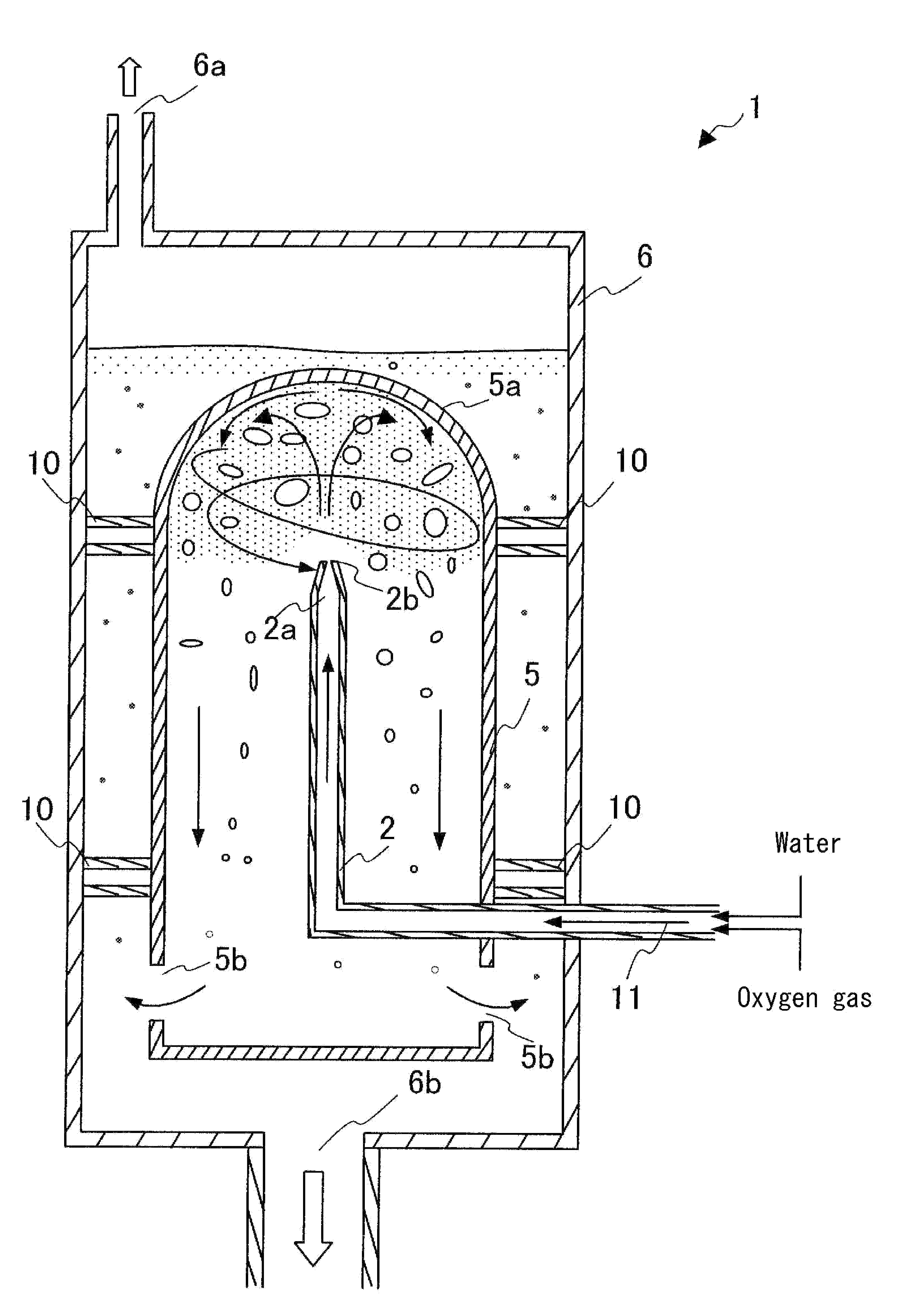
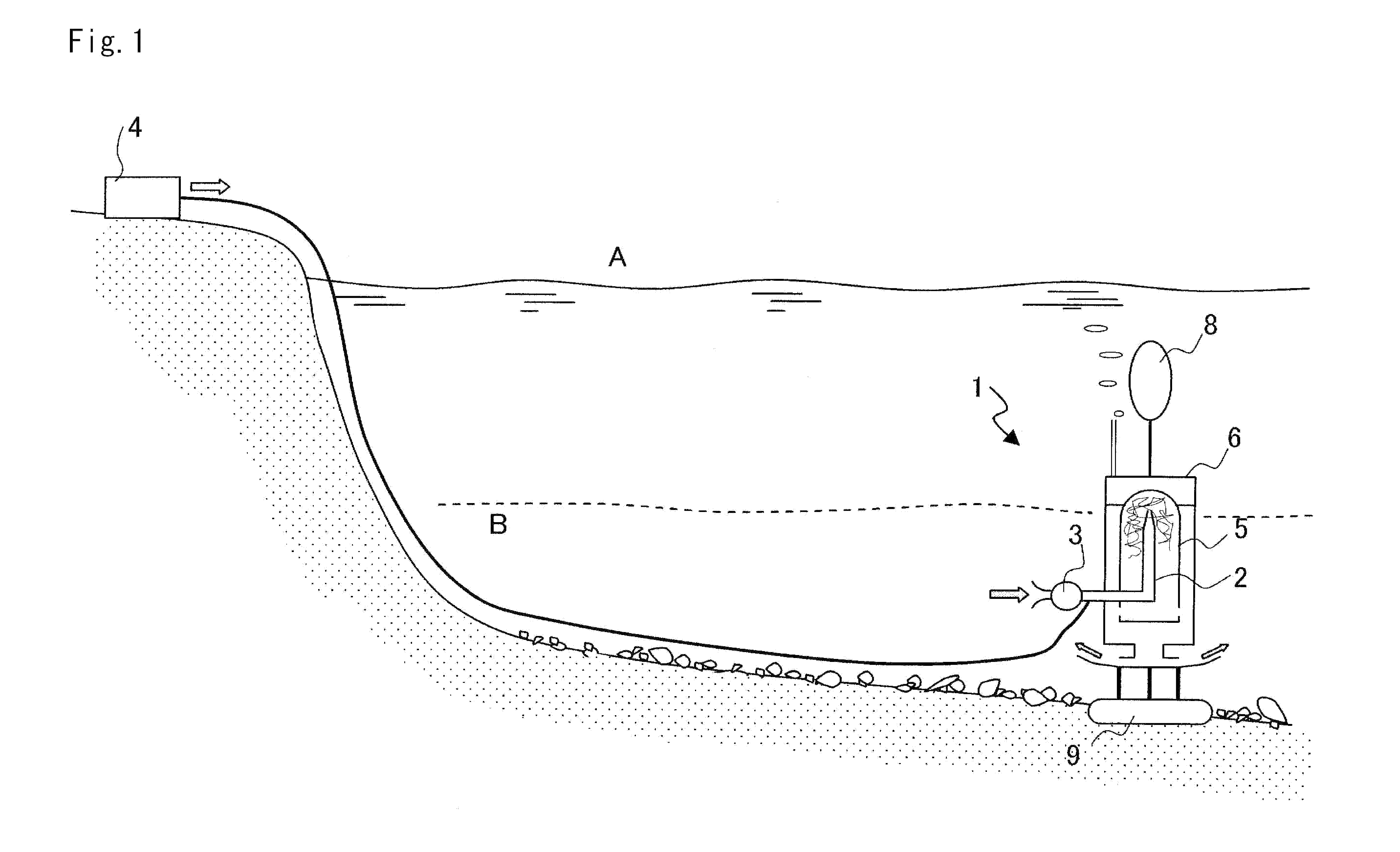
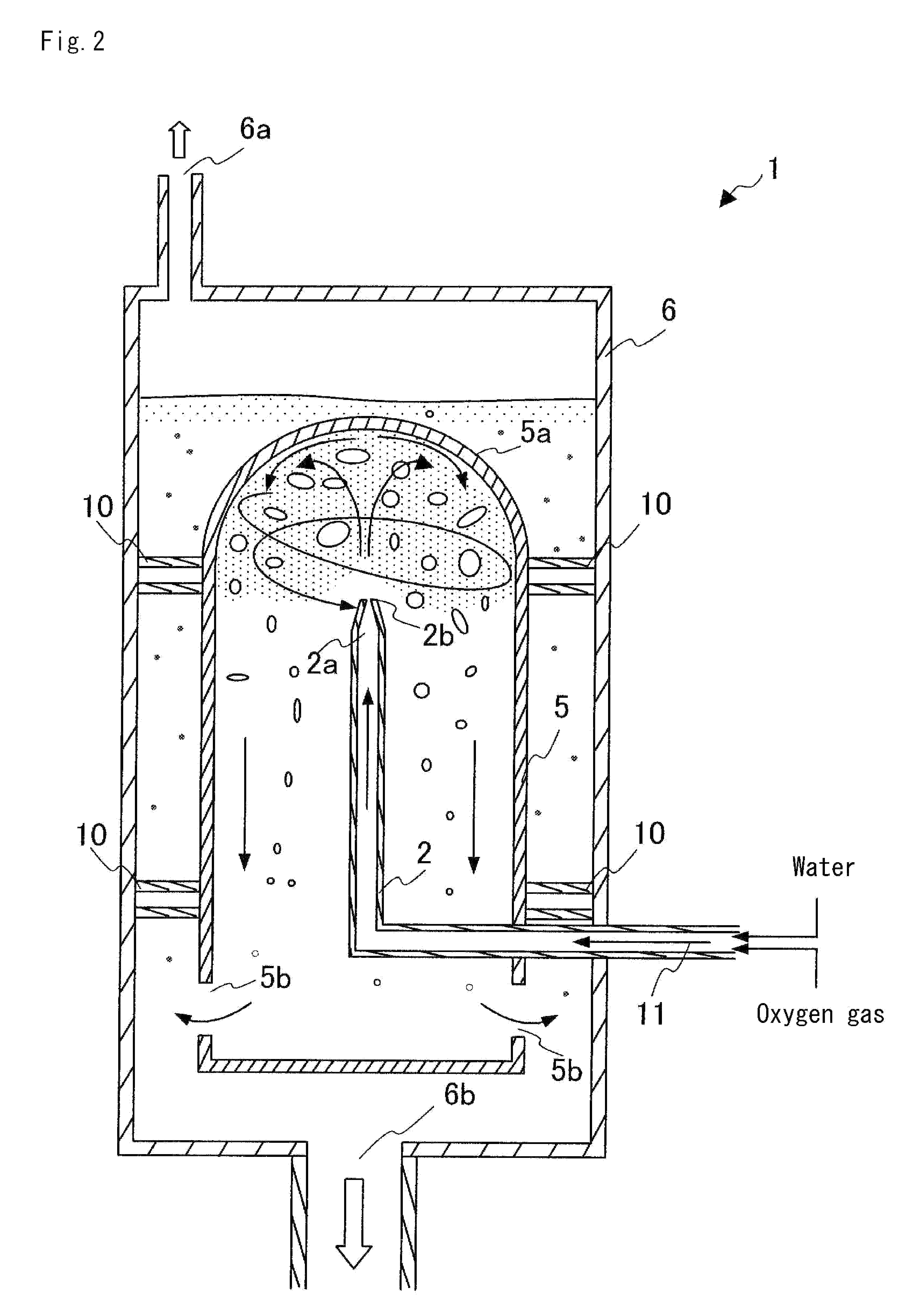
[0071]FIG. 1 is an explanatory view of an example of correction of oxygen deficiency of a lake by a gas-liquid dissolving apparatus according to the embodiment. FIG. 2 is a cross-section of an example of a schematic configuration of main parts of the gas-liquid dissolving apparatus according to the embodiment. FIG. 3 is an oblique schematic view of the main parts of the gas-liquid dissolving apparatus according to the embodiment. A gas-liquid dissolving apparatus 1 includes a pump 3 that takes in water from an oxygen-deficient water area B of a lake A and that supplies the taken-in water to a nozzle 2, an oxygen supplying unit 4 that supplies oxygen-containing gas (hereinafter, sometimes referred to as “oxygen gas” as appropriate, as which the air can be used) to the nozzle 2, the nozzle 2 that ejects the water supplied by the pump 3 and the oxygen...

first example

[0079]The oxygen-deficient water is treated by the gas-liquid dissolving apparatus and a dissolved oxygen concentration of the oxygen-deficient water is measured. FIG. 4 is a graph that depicts a change in the dissolved oxygen concentration of the water treated by the gas-liquid dissolving apparatus explained in the first embodiment against the apparatus operation time. Measurement conditions are as follows. A flow rate of the water ejected from the nozzle is 10 liters / min, a concentration of the supplied oxygen gas is 99.9% (using an oxygen cylinder), a supply amount of the oxygen gas is 0.5 liter / min, an internal pressure of the gas-liquid dissolving chamber is 0.1 megapascal (a pressure equal to approximately one atmospheric pressure), and a water temperature is 27° C. In the graph shown in FIG. 4, the dissolved oxygen concentration of the water treated by the conventional apparatus shown in FIG. 5 is also shown for comparison purposes.

[0080]The conventional apparatus shown in FI...

second embodiment

[0087]While in the first embodiment, the apparatus obtains the water into which the high concentration “oxygen” is dissolved, the present invention is not limited thereto. When a certain gas component is to be dissolved into a liquid, the same configuration as that of this apparatus can be used. The apparatus for such a purpose includes the supplying unit that supplies a gas-liquid multi-phase fluid in which the liquid and the gas are mixed up, the gas-liquid dissolving chamber that receives a flow of the gas-liquid multi-phase fluid in the upper portion and that has relief holes formed in the lower portion for releasing the fluid, the nozzle that penetrates the gas-liquid dissolving chamber and that ejects the gas-liquid multi-phase fluid supplied by the supplying unit upward toward the upper portion of the gas-liquid dissolving chamber, the gas-liquid separating chamber that is provided outside the gas-liquid dissolving chamber while communicating with the gas-liquid dissolving ch...


PUM

PropertyMeasurementUnit
concentrationaaaaaaaaaa
temperatureaaaaaaaaaa

Abstract

A gas-liquid dissolving apparatus includes an intake unit that takes in to-be-treated water from an oxygen-deficient water area, an oxygen-containing gas supply unit, a bottomed gas-liquid dissolving chamber that has at least one hole formed in a lower portion and a top plate provided in an upper portion, a nozzle that ejects the gas supplied by the supplying unit and the water supplied by the intake unit, a gas-liquid separating chamber that has a gas-vent hole formed in an upper portion and a takeout port provided in a lower portion thereof, and a water supplying unit that returns the water taken out from the takeout port to the oxygen-deficient water area.

Description

RELATED APPLICATIONS[0001]The present application is a National Phase application based on International Application Number PCT / JP2005 / 001268, filed Jan. 28, 2005, which claims priority from, Japanese Patent Application No. 2004-027318, filed Feb. 3, 2004, the disclosures of which is hereby incorporated by reference herein in its entirety.TECHNICAL FIELD[0002]The present invention relates to a gas-liquid dissolving apparatus that continuously generates liquid into which a gas component is dissolved in high concentrations. More particularly, the present invention relates to a gas-liquid dissolving apparatus that dissolves an oxygen-containing gas into water taken in from an oxygen-deficient water area to increase a dissolved oxygen concentration of the water, and that returns the water to the water area.BACKGROUND ART[0003]On a bottom layer of a lake or a marsh, a dam, a river, an inner bay, or the like, organic matters resulting from domestic wastewater or agricultural wastewater fl...

Claims


Application Information

Patent Timeline
Patent Type & Authority Patents(United States)
IPC IPC(8): B01F3/04B01F1/00B01F5/02C02F3/20C02F7/00
CPCB01F1/0022B01F3/0446B01F5/0268B01F2215/0052B01F2003/04879B01F21/20B01F23/232B01F23/237612B01F25/25B01F2101/305
Inventor KITASAKO, HIROSHIKATSUBE, MASAOSAKAMOTO, KATSUHIROSAGO, JUNZOTANAKA, HIROAKITSUMORI, JUN
Owner MATSUE DOKEN
Why Eureka
Try Eureka