
Fault-tolerant system and fault-tolerant control method

a fault-tolerant system and control method technology, applied in the field of fault-tolerant systems and fault-tolerant control methods, can solve the problems of limited fault-tolerant systems in the number, ft control lsi suffers from a bottleneck of i/o performance, and the system is involved in some restrictions in terms of hardware configuration, etc., to achieve the effect of low manufacturing cos

Inactive Publication Date: 2014-12-30
NEC CORP
View PDF12 Cites 7 Cited by
  • Summary
  • Abstract
  • Description
  • Claims
  • Application Information

AI Technical Summary

Benefits of technology

The present invention is aimed at providing a cost-effective configuration for a fault-tolerant system that includes a fault-tolerant controller connected with numerous input / output (I / O) paths. It offers a solution to connect the controller with numerous I / O paths, such as buses, links, and devices, using a low-cost manufacturing process. Overall, the invention offers a low-cost approach to create fault-tolerant control units with numerous I / O paths.

Problems solved by technology

Compared to generally-used computer systems, fault-tolerant systems are involved in some restrictions in terms of hardware configurations.
In particular, fault-tolerant systems are limited in the number of supportable I / O devices.
For this reason, the FT control LSI suffers from a bottleneck of I / O performance in response to the increasing number of I / O devices connected to each FT system.
This needs numerous high-speed interfaces in each FT control LSI chip, thus enlarging the sale of integrated circuitry and increasing cost.
Generally speaking, each FT control LSI is connected with numerous I / O paths requiring numerous high-speed interfaces, which may increase the size of an LSI chip.
LSI chips with large sizes suffer from a low yield in manufacturing and a very high manufacturing cost.

Method used


Image

  • Fault-tolerant system and fault-tolerant control method
  • Fault-tolerant system and fault-tolerant control method
  • Fault-tolerant system and fault-tolerant control method

Examples


Embodiment Construction

[0044]The present invention will be described in further detail by way of examples with reference to the accompanying drawings.

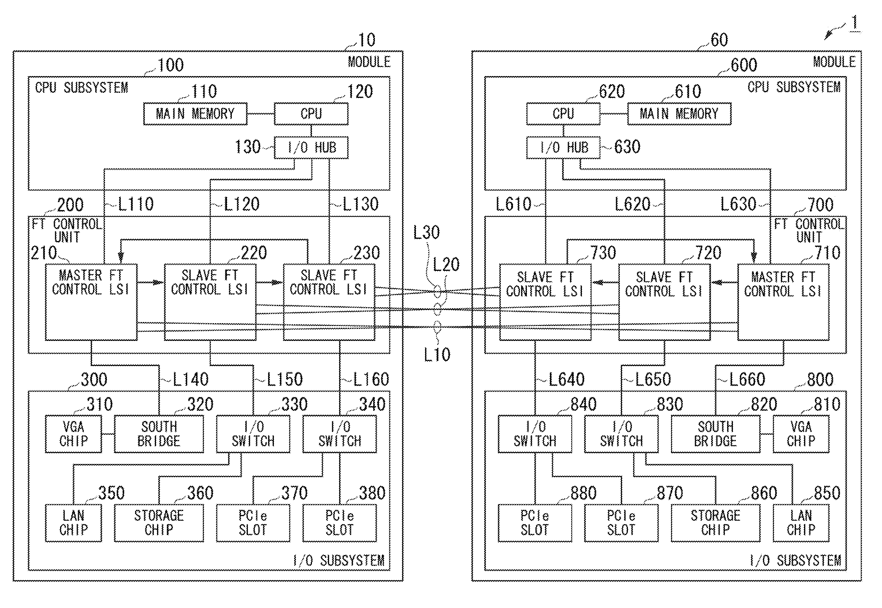
[0045]The preferred embodiment of the present invention will be described with reference to FIGS. 1 to 8, wherein the embodiment refers to a fault-tolerant server (or an FT server) which is an example of a fault-tolerant system (or an FT system) of the present invention. The fault-tolerant server is a server equipped with a fault-tolerant function, wherein a single server is multiplexed using a plurality of modules. An example of the fault-tolerant server is a PC server with a fault-tolerant function.

[0046]In this connection, the present invention is not necessarily limited to the fault-tolerant server, hence, the present invention is applicable to various types of fault-tolerant systems such as a fault-tolerant system adopting mutual communication between computers serving as modules and a fault-tolerant computer precluding a server function.

[0047]FIG. 1 is...


PUM


Abstract

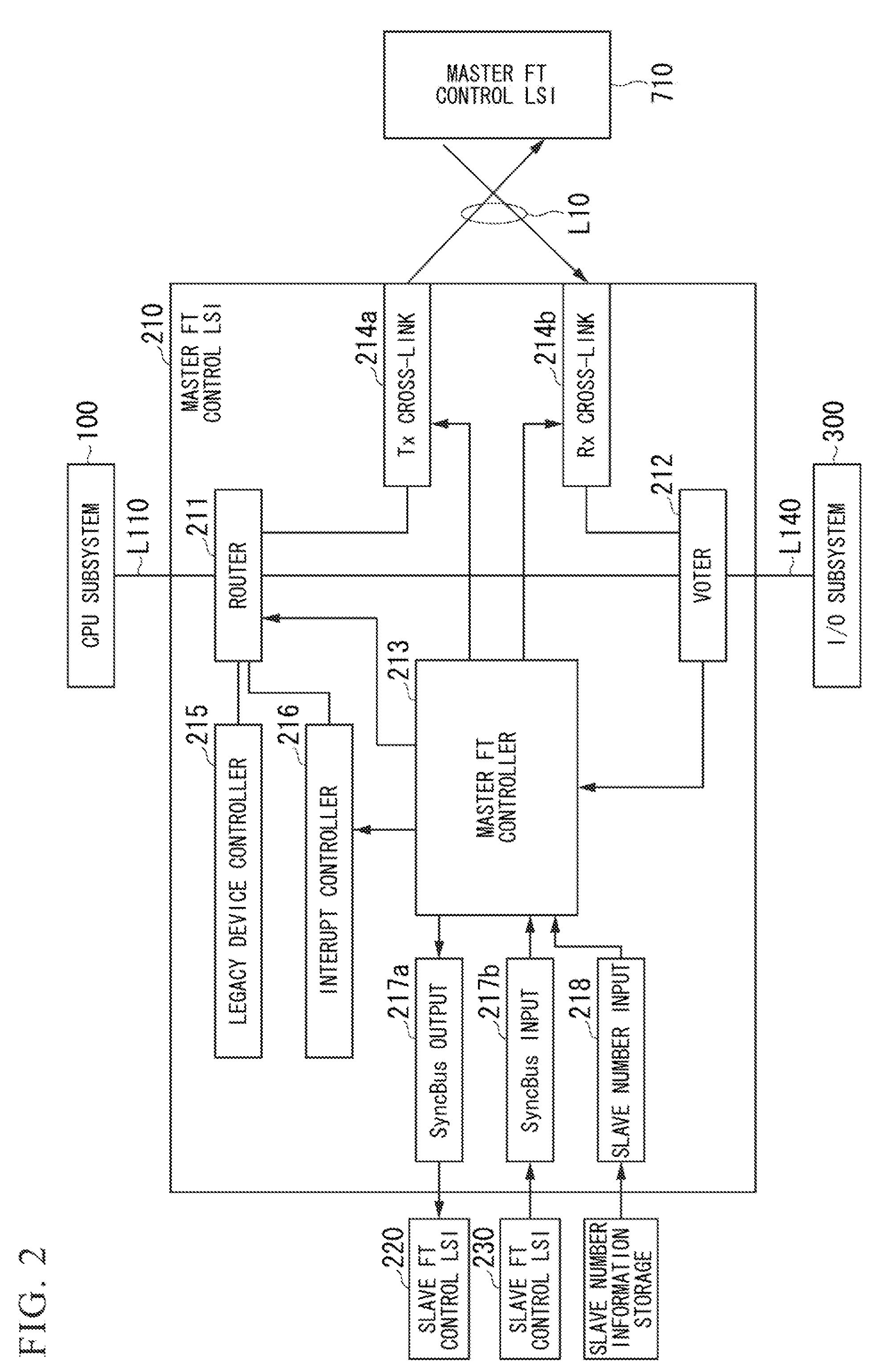
A fault-tolerant system including a plurality of modules each further including a CPU subsystem, a fault-tolerant control unit, and an I / O subsystem, wherein the fault-tolerant control unit includes a master FT control LSI chip and at least one slave FT control LSI chip. One module is placed in an active state while the other module is placed in a standby state, so that I / O requests made by CPU subsystems of these modules are selectively delivered to I / O subsystems based on the master / slave relationship. Upon receiving fault information representing a failed subsystem which is either the CPU subsystem or the I / O subsystem found in the module, the master FT control LSI chip sends a command for controlling isolation of the failed subsystem to the slave FT control LSI chip, so that the slave FT control LSI chip controls isolation of the failed subsystem based on the command.

Description

[0001]The present application claims priority on Japanese Patent. Application No. 2010-205378, the entire content of which is incorporated herein by reference.BACKGROUND OF THE INVENTION[0002]1. Field of the Invention[0003]The present invention relates to fault-tolerant systems including multiplexed subsystems, and fault-tolerant control methods applied to fault-tolerant systems.[0004]2. Description of the Related Art[0005]Fault-tolerant systems (simply referred to as FT systems) have been developed as highly-reliable computer systems. For instance, Patent Document 1 discloses a fault-tolerant computer system, adopting an existing operating system (OS) precluding a duplex-redundancy functionality, which provides duplex fault-tolerant configurations each including a CPU, a VGA, and an I / O device. Upon occurrence of a fault, a routing controller rewrites an address of a request issued by the CPU so as to conceal duplex-redundancy functionality from the CPU.[0006]Fault-tolerant systems...

Claims


Application Information

Patent Timeline
Patent Type & Authority Patents(United States)
IPC IPC(8): G06F11/16G06F11/20G06F11/00
CPCG06F11/2038G06F11/2028G06F11/1654G06F11/1645
Inventor ABE, SHINJI
Owner NEC CORP
Learn More