Arrangement to supply a sensor with electrical power

a technology of electrical power supply and sensor, which is applied in the direction of electric generator control, machines/engines, transportation and packaging, etc., can solve the problems of damage to the external power supply psu and other electronic systems of the system

Inactive Publication Date: 2012-04-05
SIEMENS AG
View PDF5 Cites 0 Cited by
  • Summary
  • Abstract
  • Description
  • Claims
  • Application Information

AI Technical Summary

Benefits of technology

[0033]The arrangement is cheap and might be brought into already existing and even mounted blades even later. Thus a retrofit of existing blades is ensured very easily.

Problems solved by technology

Its external power supply PSU and other electronic systems might be damaged by the lightning passing through the cables PC.

Method used


Image

  • Arrangement to supply a sensor with electrical power
  • Arrangement to supply a sensor with electrical power
  • Arrangement to supply a sensor with electrical power

Examples


Embodiment Construction

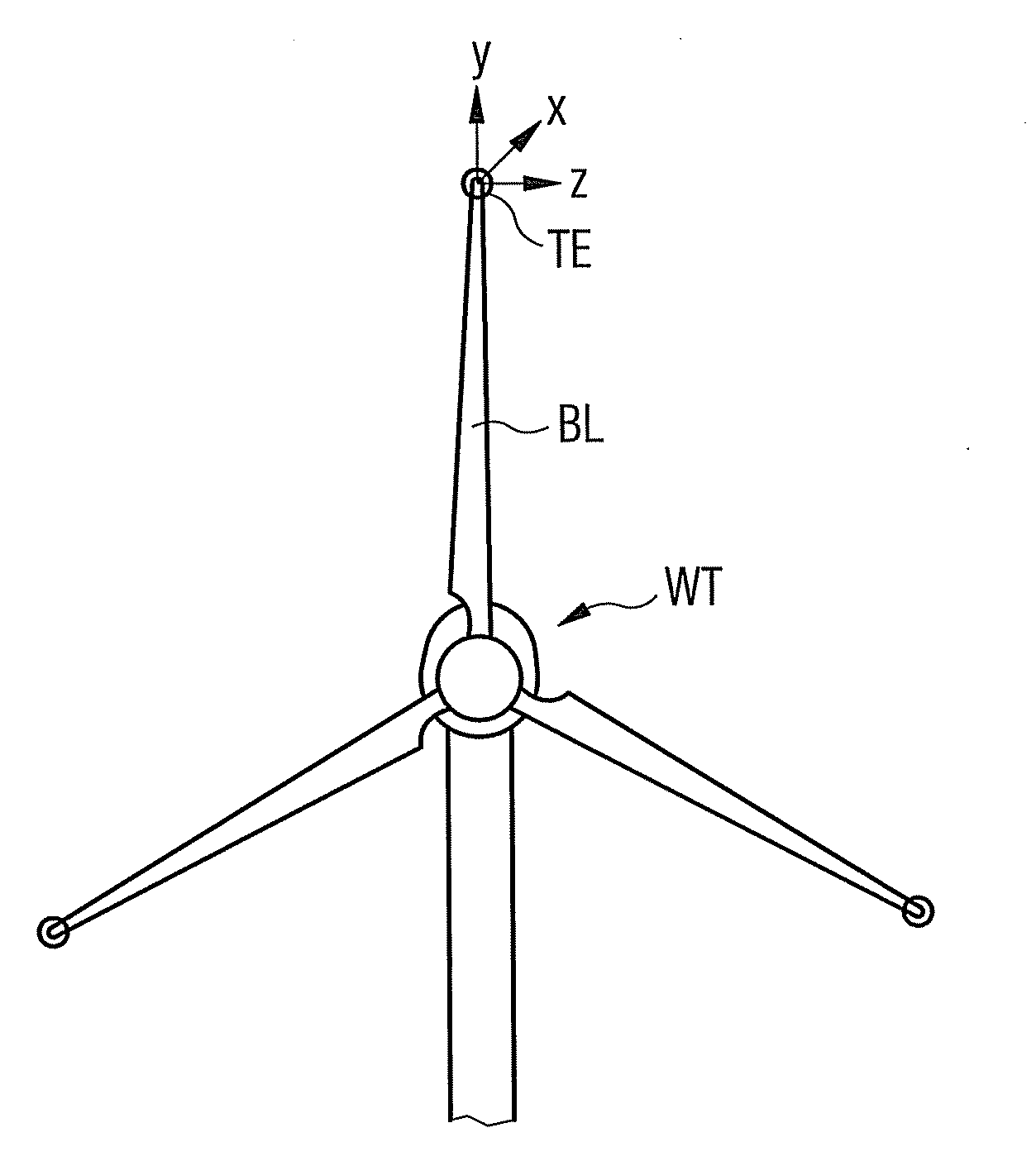
[0041]FIG. 1 shows a wind turbine WT, which is fitted according to the invention.

[0042]The kinetic charger and the component (as shown in FIG. 2) are preferably arranged close to the tip end TE of the blade BL.

[0043]The tip end TE moves in three dimensions x, y and z—even if the blade BL is turning or not.

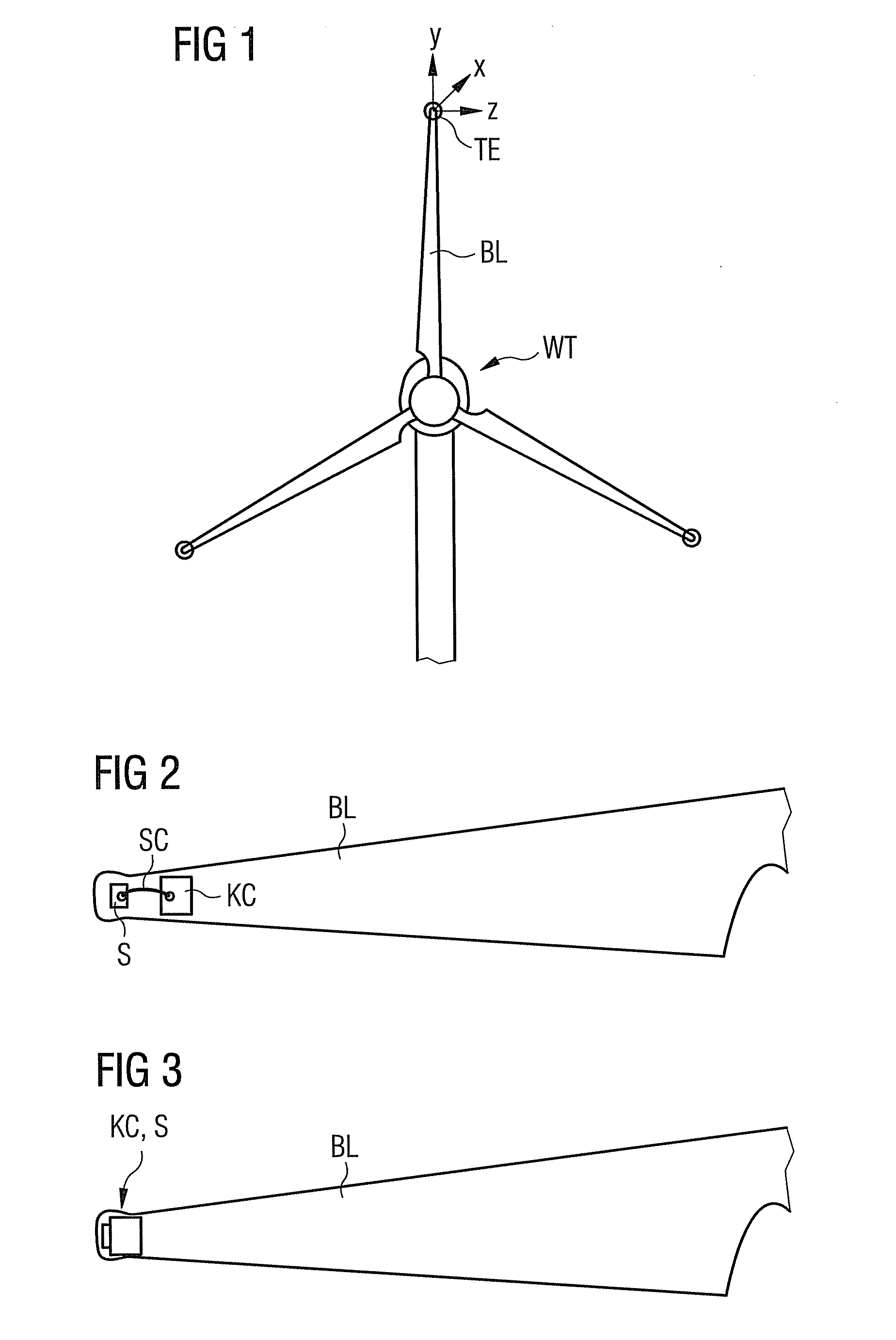
[0044]FIG. 2 shows a first configuration of the arrangement invented.

[0045]A sensor S is located as electrical component asides the blade BL.

[0046]Preferably the sensor S is located within a cavity (not shon in detail) of the blade BL.

[0047]Preferably the sensor S is arranged close to the tip end of the blade BL.

[0048]The kinetic charger KC is connected with the sensor S by short cables SC. A lightning may not strike the cables SC due their short length.

[0049]FIG. 3 shows a second configuration of the arrangement invented.

[0050]The kinetic charger KC and the sensor S are preferably arranged into a common housing. Thus they are an integrated part of each other.

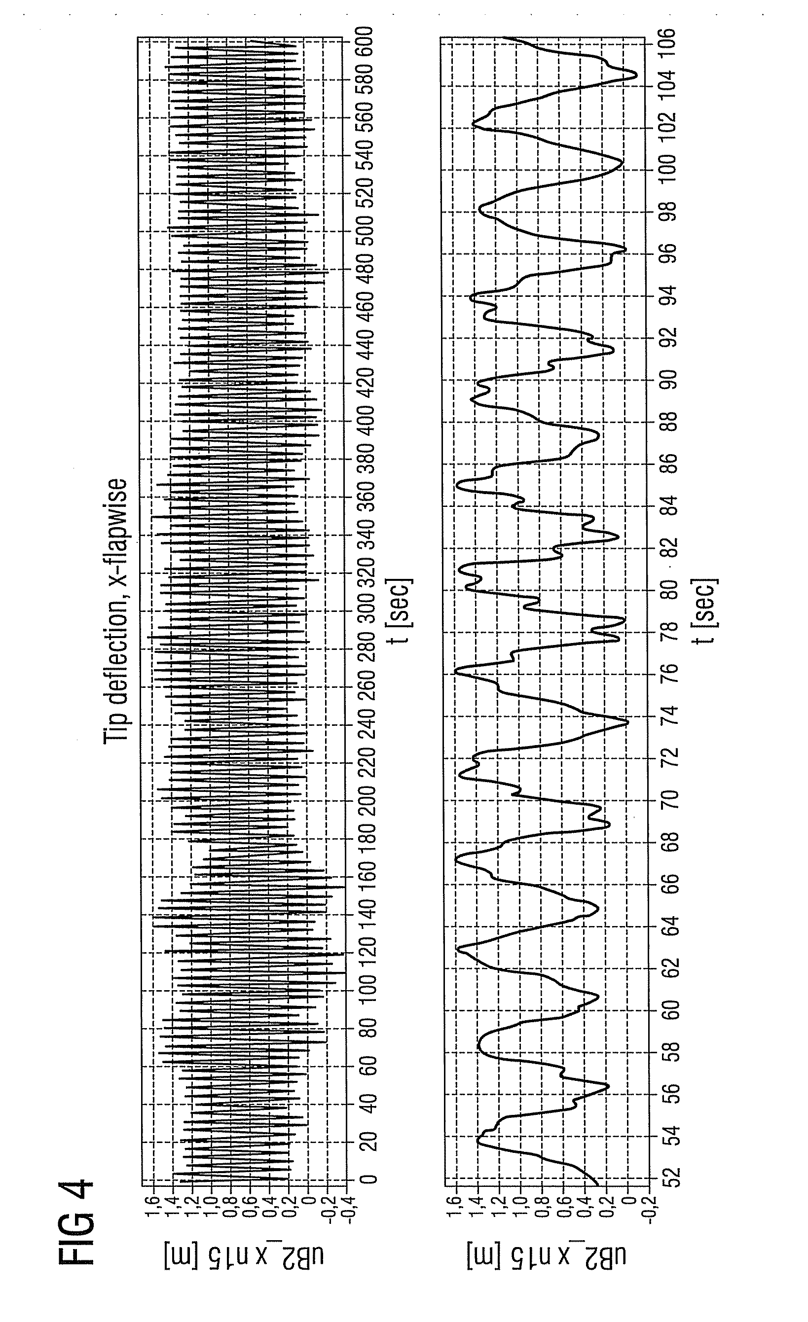
[0051]FIG. 4 and FIG. ...


PUM


Abstract

An arrangement to supply an active electrical component with electrical power is proposed. The component is arranged asides a wind turbine blade. A kinetic charger is connected with the component. The kinetic charger is designed and constructed to transform mechanical movements of the blade into electrical power, while the power generated by the kinetic charger is supplied to the component.

Description

CROSS REFERENCE TO RELATED APPLICATIONS[0001]This application claims priority of European application No. 10186400 filed Oct. 4, 2010, which is incorporated by reference herein in its entirety.FIELD OF THE INVENTION[0002]The invention relates to an arrangement to supply an active electrical component with electrical power, while the component is arranged asides a wind turbine blade.BACKGROUND OF THE INVENTION[0003]It is known to use an active electrical component, which is arranged asides a wind turbine blade.[0004]This kind of electrical component needs to be supplied with electrical energy.[0005]It is possible to supply the component by electrical lines like cables. The cables are guided from an external power supply through the hub of the wind turbine and to the component asides the blade.[0006]This situation is shown in FIG. 6, where a sensor S is arranged as active electrical component within a blade BL. The sensor S is supplied with electrical power by a power supply unit PSU....

Claims


Application Information

Patent Timeline
Patent Type & Authority Applications(United States)
IPC IPC(8): F03G7/08H02J7/34
CPCF03D11/00Y02E10/722F05B2260/96F05B2260/80F03D80/00Y02E10/72F03D9/25F03D17/00
Inventor ANDERSEN, JIMMI
Owner SIEMENS AG
Why Eureka
Try Eureka