Monitoring system with a camera and non-metallic mirror for magnetic resonance examination system

a technology of magnetic resonance examination and camera, which is applied in the direction of measuring using nmr, magnetic variable regulation, instruments, etc., can solve the problems of auxiliary equipment placed, parts of the patient's body to be examined may also create obstacles, and the proportion at issue would be blocked from the camera's rang

Pending Publication Date: 2022-11-17
KONINKLJIJKE PHILIPS NV
View PDF0 Cites 0 Cited by
  • Summary
  • Abstract
  • Description
  • Claims
  • Application Information

AI Technical Summary

Problems solved by technology

Notably, if no steps were taken, the portion at issue would be blocked from the camera's range.
Such an obstacle is formed by an opaque object located in the camera's direct lines of sight into the examination zone.
Such an obstacle may be auxiliary equipment that is placed

Method used


Image

  • Monitoring system with a camera and non-metallic mirror for magnetic resonance examination system
  • Monitoring system with a camera and non-metallic mirror for magnetic resonance examination system
  • Monitoring system with a camera and non-metallic mirror for magnetic resonance examination system

Examples


Embodiment Construction

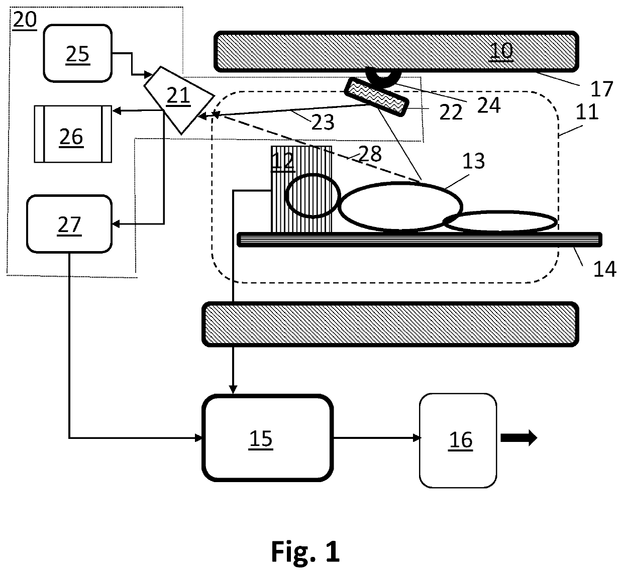
[0029]FIG. 1 shows a schematic side-elevation of an example of the magnetic resonance examination system incorporating the invention. The magnetic resonance examination system comprises a main magnet structure 10, which defines the examination zone. A patient to be examined 13 may be positioned on a patient carrier 14, e.g. a patient couch, into the examination zone. The main magnet structure includes a frame holding magnet windings to generate a stationary uniform magnetic field in the examination zone. The examination zone may be a cylindrical volume encompassed by a set of coaxial (super conductive) windings. The acquired magnetic resonance signals are applied to a reconstructor 15 which reconstructs magnetic resonance image(s) from the magnetic resonance signals. The reconstructed magnetic resonance images are finally output 16 for viewing, processing or storage. Auxiliary equipment, such as the RF T / R head coil 12 is placed in the examination zone, notably to acquire magnetic r...


PUM


Abstract

A magnetic resonance examination system with an examination zone (11) and comprising a camera (21) and non-metallic mirror (22), in particular within the examination zone (11), arranging an optical pathway (23) between a portion of the examination zone (11), via the non-metallic mirror (22), and the camera (21). The camera can obtain image information from that portion even if the direct line of sight (28) is blocked. The non-metallic mirror is a dielectric mirror having a macroscopically grated base.

Description

FIELD OF THE INVENTION[0001]The invention pertains to a monitoring system with a camera to monitor the examination region of a magnetic resonance examination system.BACKGROUND OF THE INVENTION[0002]Such a monitoring system is known from the US-patent application US2017 / 0146619. The known monitoring system is formed by a camera that is mounted outside the magnetic resonance imaging (MM) device's bore, adjacent to the MRI-device's protective cover. The camera is arranged to image the patient to be examined during operation of the MM-device.[0003]JP H0928689 discloses a mirror installed in the bore of an MRI system and a TV camera for taking an image of a subject mirrored on the mirror. A computer analyzes the image and detects the motion of the subject. The computer determines whether the MR data is to be discarded, taken again or collected, e.g. depending on whether the subject moves out of a limited range. Alternatively, MRI parameters can be optimized to cancel the influence of the...

Claims


Application Information

Patent Timeline
IPC IPC(8): G01R33/28G01R33/56
CPCG01R33/283G01R33/56G02B5/0825A61B5/055A61B5/004A61B5/0077G01R33/5673G02B5/09
Inventor WEISS, STEFFENWUELBERN, JAN HENDRIKLEUSSLER, CHRISTOPH GÜNTHERSENEGAS, JULIEN THOMAS
Owner KONINKLJIJKE PHILIPS NV
Why Eureka
Try Eureka