Adaptive zero current sense apparatus and method for a switching regulator

a zero current sense and switching regulator technology, applied in the direction of electric variable regulation, process and machine control, instruments, etc., can solve the problem that the pre-set zero current threshold becomes unsuitable for the real conditions

Active Publication Date: 2008-10-09
RICHTEK TECH
View PDF15 Cites 60 Cited by
  • Summary
  • Abstract
  • Description
  • Claims
  • Application Information

AI Technical Summary

Benefits of technology

[0009]Advantageously, the proposed apparatus and method can prevent reverse inductor current from the output terminal of a switching regulator, and also control the body-diode turn-on time of the low-side switch within a given value.

Problems solved by technology

However, the zero-current threshold Ith of the conventional zero-current sense circuit 108 is fixed but not adjustable when it is designed, and in the event that the output voltage Vout or the inductor L is changed, causing the falling slope slope_fall of the inductor current IL changed, the pre-set zero-current threshold Ith becomes not suitable to the real conditions.

Method used


Image

  • Adaptive zero current sense apparatus and method for a switching regulator
  • Adaptive zero current sense apparatus and method for a switching regulator
  • Adaptive zero current sense apparatus and method for a switching regulator

Examples


Embodiment Construction

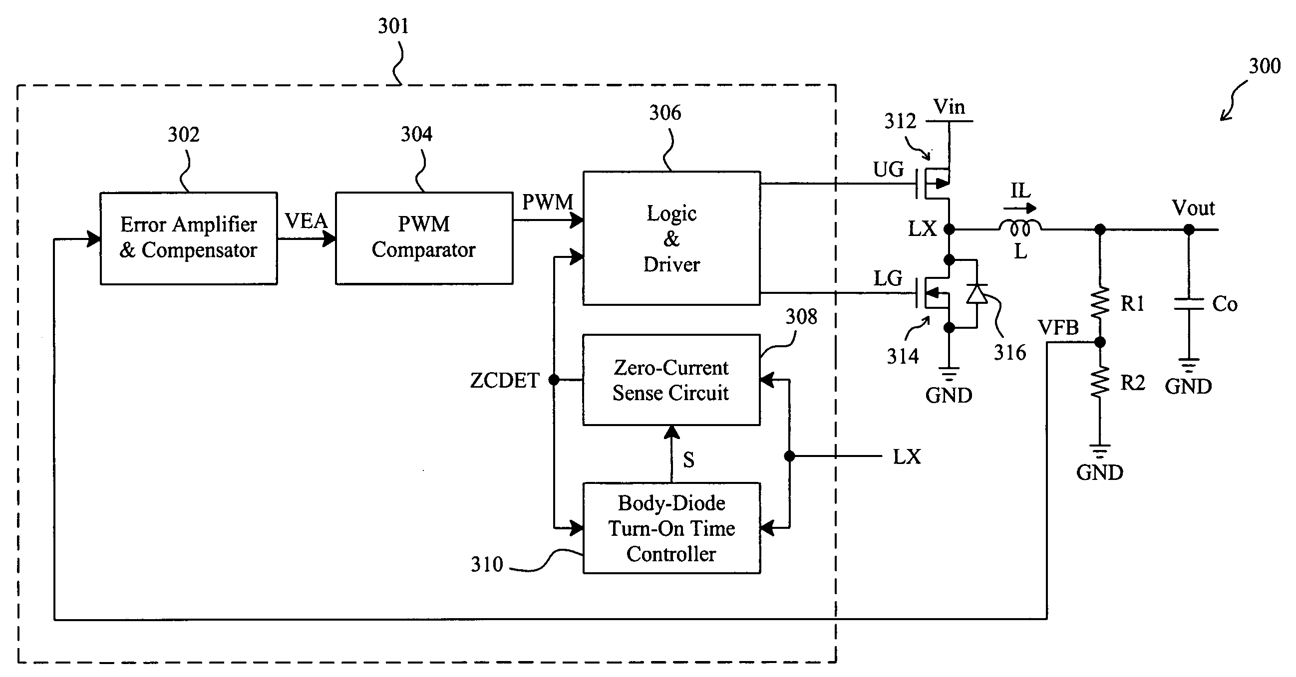
[0024]As shown in FIG. 7, in a switching regulator 300, a controller 301 switches a high-side switch 312 and a low-side switch 314 connected in series between a power input terminal Vin and a ground terminal GND, to generate an inductor current IL that charges a capacitor Co to produce an output voltage Vout, the low-side switch 314 has a body diode 316, and voltage divider resistors R1 and R2 are connected in series between the output terminal Vout and the ground terminal GND, to generate a feedback voltage VFB for the controller 301 to regulate the output voltage Vout. In the controller 301, an error amplifier and compensator unit 302 generates an error signal VEA according to the feedback voltage VFB, a PWM comparator 304 generates a PWM signal according to the error signal VEA to provide for a logic and driver unit 306 to drive the switches 312 and 314, a zero-current sense circuit 308 monitors the inductor current IL by monitoring the voltage on the phase node LX and triggers a...


PUM


Abstract

A switching regulator includes a low-side switch having a body diode. During the low-side switch is on, a zero-current sense circuit monitors the inductor current of the switching regulator and triggers a signal to turn off the low-side switch when the inductor current falls down to a zero-current threshold, to prevent reverse inductor current from the output terminal of the switching regulator. A body-diode turn-on time controller monitors the turn-on time of the body diode and adjusts the zero-current threshold according thereto, and the turn-on time of the body diode can be reduced to an optimal interval subsequently. The self-adjustable zero-current threshold is adaptive according to the application conditions, such as the inductor size, input voltage and output voltage of the switching regulator.

Description

FIELD OF THE INVENTION[0001]The present invention is related generally to a switching regulator and, more particularly, to a zero-current sense apparatus and method for a switching regulator.BACKGROUND OF THE INVENTION[0002]According to the inductor current condition, switching regulators can be generally categorized into two types: Continuous Conduction Mode (CCM) and Discontinuous Conduction Mode (DCM). FIGS. 1 and 2 are waveform diagrams of the ideal inductor currents in CCM and DCM switching regulators, respectively, and both the modes have respective advantages and applications. FIG. 3 shows a conventional DCM synchronous buck switching regulator 100, in which a controller 101 switches a high-side switch 110 and a low-side switch 112 connected in series between a power input terminal Vin and a ground terminal GND to generate an inductor current IL that charges a capacitor Co to produce an output voltage Vout, and voltage divider resistors R1 and R2 are connected in series betwe...

Claims


Application Information

Patent Timeline
Patent Type & Authority Applications(United States)
IPC IPC(8): G05F1/565
CPCH02M3/1588H02M2001/0009Y02B70/1466H02M1/0009Y02B70/10
Inventor CHU, KWAN-JENKUNG, NIEN-HUICHIU, TZU-HUANLU, CHIEN-PING
Owner RICHTEK TECH
Why Eureka
Try Eureka