Short Range Radar and Method of Controlling the Same

a short-range radar and short-range technology, applied in the field of short-range radars, can solve the problems of leakage, difficult to prevent carrier, and inability to completely stop the outputting of carrier signals

Inactive Publication Date: 2008-10-09
ANRITSU CORP
View PDF19 Cites 19 Cited by
  • Summary
  • Abstract
  • Description
  • Claims
  • Application Information

AI Technical Summary

Benefits of technology

[0104]However, as the configuration in which the first burst wave is delayed by the predetermined time by means of the fixed de

Problems solved by technology

However, as in the conventional short range radar, in the configuration in which the switch circuit 2 set in the path for the carrier signal CA is turn on or off to generate the burst wave Ba, the following problem is posed.
That is, leakage occurs due to incomplete isolation of the switch circuit 2, and outputting of the carrier signal cannot be completely stopped.
In particular, in the UWB having a high frequency, it is difficult to

Method used


Image

  • Short Range Radar and Method of Controlling the Same
  • Short Range Radar and Method of Controlling the Same
  • Short Range Radar and Method of Controlling the Same

Examples


first embodiment

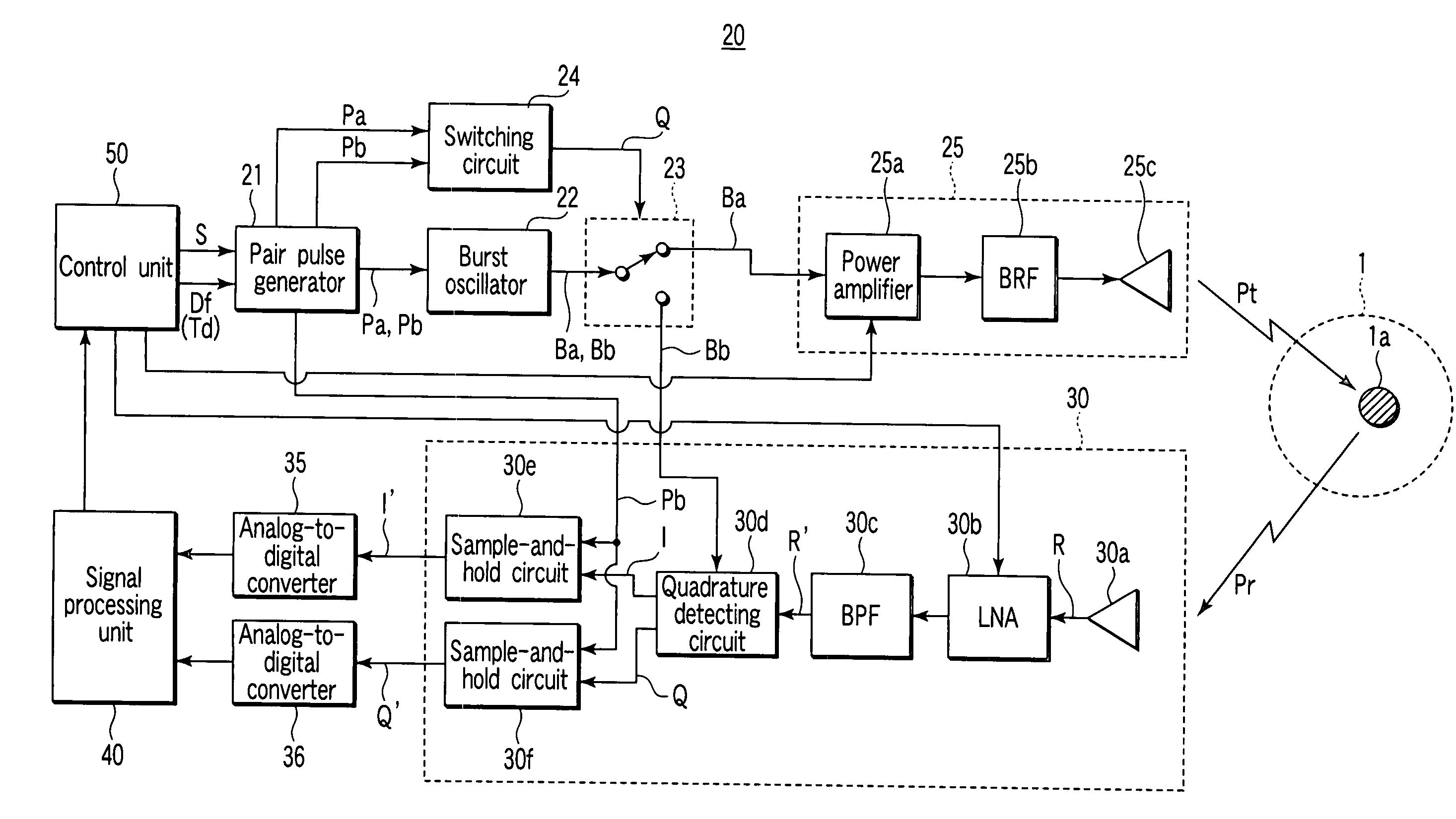
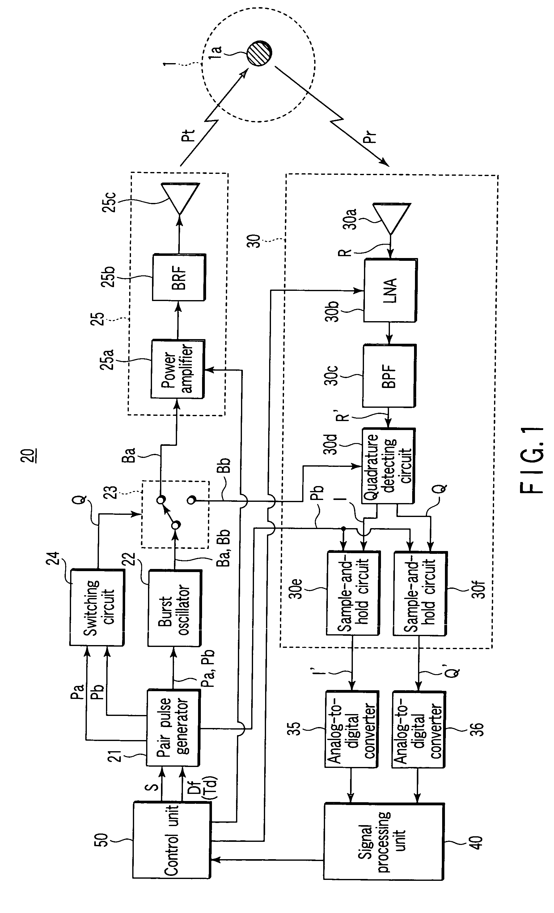
[0121]FIG. 1 is a block diagram shown to explain a configuration of a short range radar according to a first embodiment of the present invention.

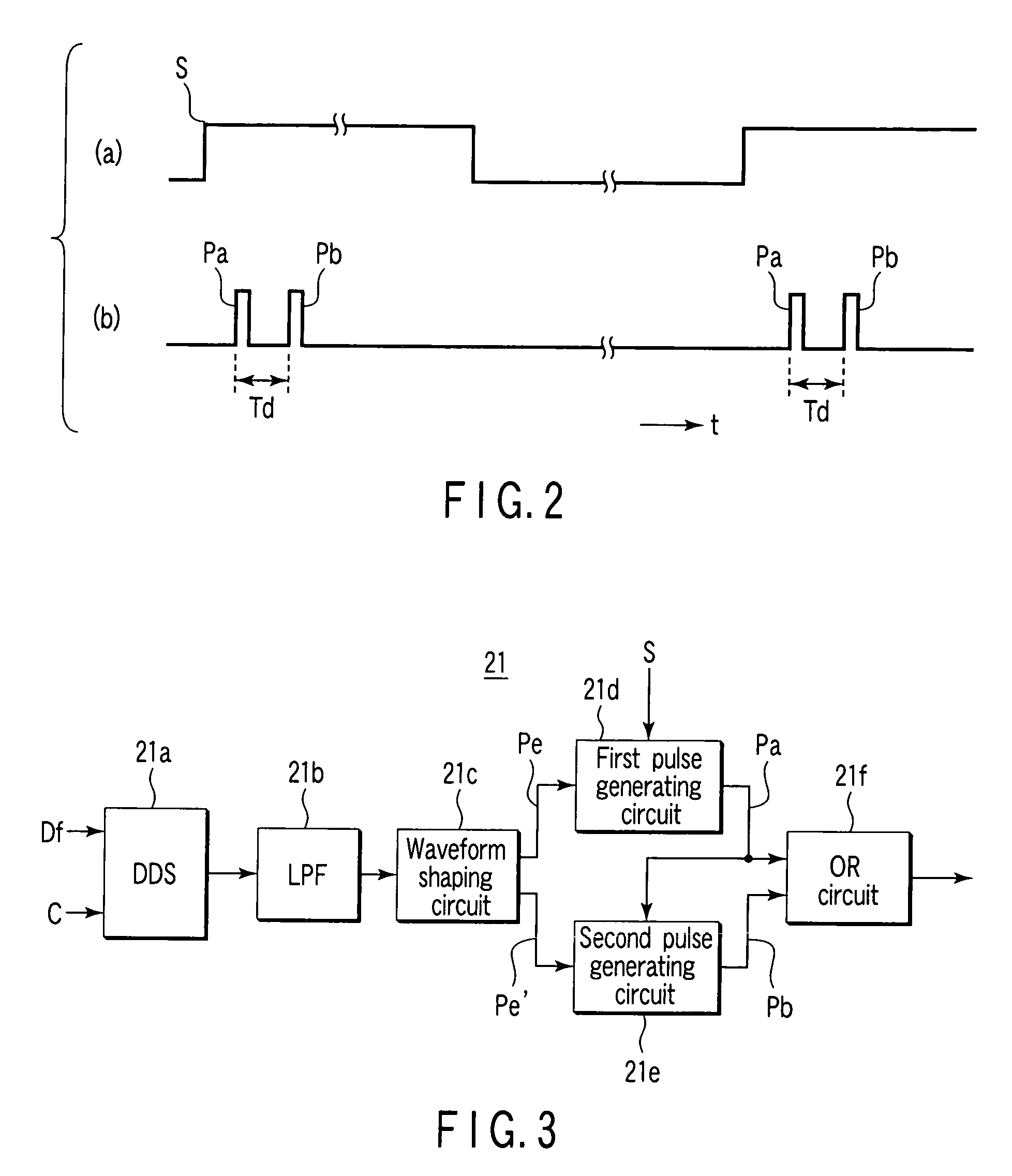
[0122]A short range radar 20 according to the present invention basically includes: a pair pulse generator 21 which generates one pair of pulses including a pulse signal Pa having a predetermined width and a second pulse Pb having a width equal to that of the first pulse and being behind from the first pulse by preset time Td each time the pair pulse generator 21 receives a transmission designation signal S; a burst oscillator 22 which performs an oscillation operation in a period in which one pair of pulses including the first and second pulses Pa and Pb output from the pair pulse generator 21 are received to output a signal having a predetermined carrier frequency as a first burst wave Ba in synchronism with the pulse signal Pa and also output the signal of the predetermined carrier frequency as a second burst wave Bb in synchronism with ...

second embodiment

[0205]FIG. 12 is a block diagram shown to explain a configuration of a short range radar 20′ according to a second embodiment of the present invention.

[0206]The same reference numerals as in the configuration of the short range radar 20 according to the first embodiment shown in FIG. 1 denote the same parts in the configuration in FIG. 12, and a description thereof will be omitted.

[0207]In the first embodiment, the first pulse Pa and the second pulse Pb and the second pulse Pb are generated in synchronism with timings of a rising edge and a decaying edge of a variable cycle pulse Pe. For this reason, the cycle of the variable cycle pulse Pe must be shortened to, e.g., 1 ns to make the interval between a first pulse Pa and a second pulse Pb zero. The short range radar 20′ may not be difficult to be realized, and very short-distance exploration may be difficult.

[0208]Even though pairs of pulses having short intervals can be generated by a pair pulse generator 21, a switching speed of ...


PUM


Abstract

A pair pulse generator generates one pair of pulses including a first pulse having a predetermined width and a second pulse having a width equal to that of the first pulse and being behind from the first pulse by preset time each time a transmission designation signal is received. A burst oscillator performs an oscillation operation in a period in which one pair of pulses are input to output a signal having a predetermined carrier frequency as a first burst wave in synchronism with the first pulse and also output the signal of the predetermined carrier frequency as a second burst wave in synchronism with the second pulse, and stops the oscillation operation in a period in which one pair of pulses are not input. A transmitting unit emits the first burst wave into an exploration target space as a short pulse wave. A receiving unit receives a reflected wave and detects the second burst wave as a local signal. A control unit variably controls an interval between the first pulse and the second pulse.

Description

TECHNICAL FIELD[0001]The present invention relates to short range radars and a method of controlling the same, and more particularly, to, of short range radars which emit a pulse wave having a short width (short pulse wave) into space at a predetermined frequency, receives and detects a reflected wave from an object existing in the space, and analyzes the object existing in the space based on the detection output, a short range radar to be used in an ultra-wide band (UWB) ranging from 22 to 29 GHz allocated to automotive radars or radars for people with visual impairment, the short range radar employing a technique to make it possible to cause a short range radar to correctly conform to the rules of International Radio Communication Regulations (RR), and a method of controlling the same.BACKGROUND ART[0002]A short range radar using a UWB is tried to be practically used as an automotive short range radar or a radar for people with visual impairment.[0003]A short range radar using a U...

Claims


Application Information

Patent Timeline
IPC IPC(8): G01S13/00
CPCG01S7/023G01S13/0209G01S13/106G01S2007/2886G01S7/2886G01S7/0235
Inventor TESHIROGI, TASUKUUCHINO, MASAHARUSAITO, SUMIOEJIMA, MASANORI
Owner ANRITSU CORP
Why Eureka
Try Eureka