Antenna Arrangement

Active Publication Date: 2008-10-09
CUBIC CORPORATION
View PDF11 Cites 16 Cited by
  • Summary
  • Abstract
  • Description
  • Claims
  • Application Information

AI Technical Summary

Benefits of technology

[0009]individually controllable gain control element

Problems solved by technology

However, if the cells are too large then, since the available communications frequencies are reused in multiple cells, there will be in

Method used


Image

  • Antenna Arrangement
  • Antenna Arrangement
  • Antenna Arrangement

Examples


Embodiment Construction

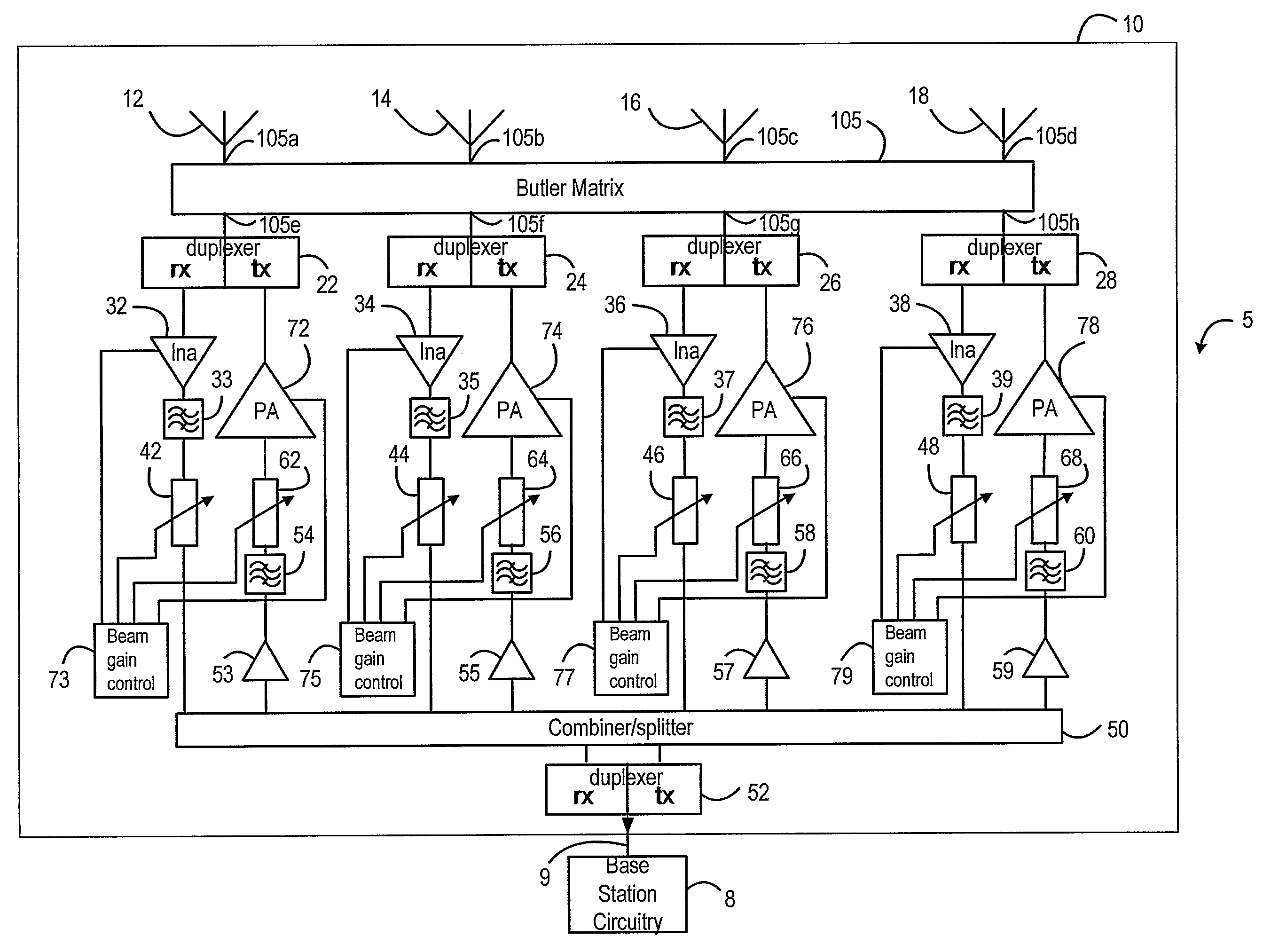
[0038]FIG. 1 shows a base station 5 including generally conventional base station circuitry 8 and an antenna 10 in accordance with the present invention. As is well known, a base station of a cellular wireless communications network can be located in the centre of the cell that it is serving, in which case an omnidirectional antenna is required, or it can be located adjacent two or more cells, in which case it requires a directional antenna for each of the cells that it is serving. The invention will be described herein with reference to its use in an omnidirectional antenna. However, it will be apparent that the invention can also be applied to a directional antenna.

[0039]As shown in FIG. 1, the base station 5 includes one antenna 10, although it could include more than one such antenna, and, in that case, each of the antennas may be omnidirectional or directional.

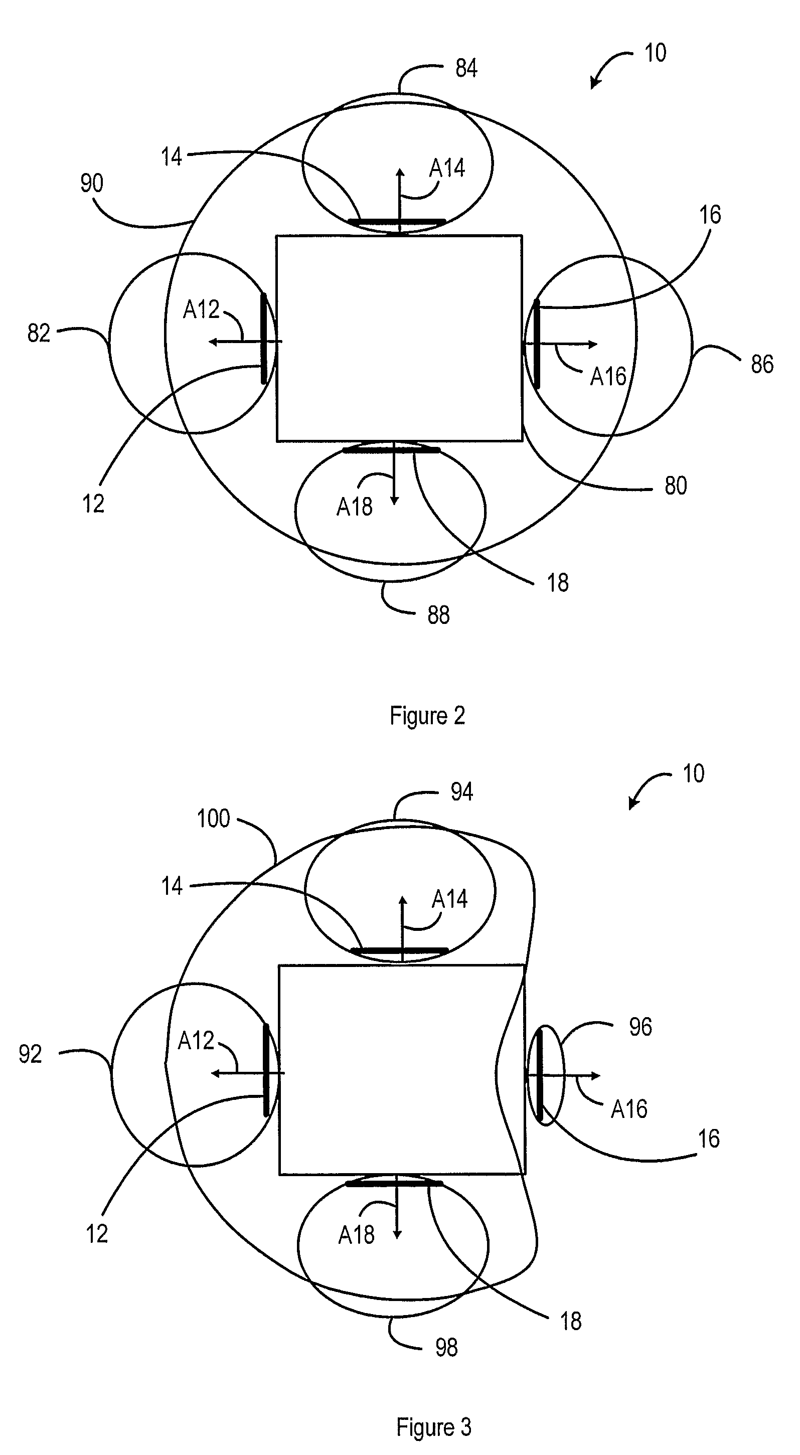
[0040]The antenna 10 includes four antenna elements 12, 14, 16, 18, each of which provides a part of the omnidirectiona...


PUM


Abstract

An antenna has multiple antenna elements, with a beam forming Butler matrix, having antenna ports and input/output ports, with each of said antenna elements being connected to a respective port of the beam forming Butler matrix. Transceiver circuitry is connected to each of the input/output ports of the beam forming matrix by means of respective distinct transmit and receive paths and a respective duplexer. Individually controllable gain control elements are located in each of the transmit and receive paths. These can be controlled in response to signal strength measurements made by the antenna.

Description

TECHNICAL FIELD OF THE INVENTION[0001]This invention relates to an antenna arrangement, and in particular to a self-installable antenna arrangement with a controllable field pattern.BRIEF DISCUSSION OF RELATED ART[0002]In a wireless communications network, such as a mobile communications network in which portable devices are able to communicate over radio channels, the operator provides a network of base stations. Each of the base stations has one or more antennas, and is able to communicate with portable devices in one or more cells, such that the cells together provide coverage over the whole service area of the network. The extent of each cell depends on the properties of the antenna that provides the coverage for that cell. If the antenna transmits signals with high power, and receives signals with high sensitivity, the cell is relatively large, while if the antenna transmits signals with low power, and receives signals with low sensitivity, the cell is relatively small.[0003]Th...

Claims


Application Information

Patent Timeline
IPC IPC(8): H01Q3/00H01Q21/00H04B1/38H04B7/005H01Q3/26H01Q3/40H01Q25/00
CPCH01Q3/2652H01Q3/40H01Q25/00
Inventor FOX, ANDREW JOHN
Owner CUBIC CORPORATION
Why Eureka
Try Eureka