Optical transmission module and optical patch cable

a technology which is applied in the field of optical transmission module and optical patch cable, can solve the problems of increasing the size of the entire module, the number of its components, and the cost of the equipment, and the inability to meet the requirements of optical or electrical components, and achieves the effect of convenient mounting of components to the cas

Inactive Publication Date: 2008-10-09
HITACHI CABLE
View PDF22 Cites 34 Cited by
  • Summary
  • Abstract
  • Description
  • Claims
  • Application Information

AI Technical Summary

Benefits of technology

[0057]According to this invention, it is possible to provide a small-size and inexpensive optical trans...

Problems solved by technology

Namely, because the conventional optical transmission module 131 only performs transmission or reception with one optical fiber, there are the problems of increases in its entire module size, the number of its components, and in its cost, when it is used in Infiniband (registered trademark), which is a high-speed interface standard specified for servers.
Also, optical transmission modules are required to be further enhance...

Method used


Image

  • Optical transmission module and optical patch cable
  • Optical transmission module and optical patch cable
  • Optical transmission module and optical patch cable

Examples


Embodiment Construction

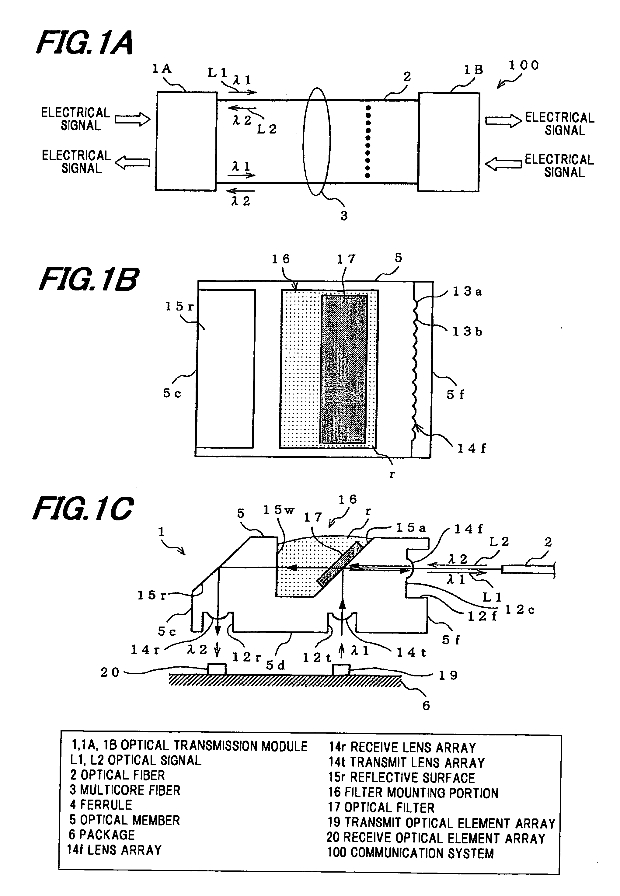
[0076]First explained is a communication system using an optical transmission module in a preferred embodiment according to the invention, shown by FIG. 1A.

[0077]As shown in FIG. 1A, a communication system 100 connects optical transmission modules (multicore bidirectional optical transmission modules, or active connector modules) 1A and 1B (herein, also referred to as optical transmission module 1) in this embodiment, which convert an electrical / optical to optical / electrical signal, with a multicore fiber 3 comprising plural parallel arrayed optical fibers 2 for transmitting different wavelength optical signals, and converts an electrical / optical to optical / electrical signal, for transmission / reception between the optical transmission modules 1A and 1B.

[0078]This embodiment uses twelve multimode fibers (MMFs) as the optical fibers 2, which are arrayed parallel as twelve transmission channels to form a tape fiber which is used as the multicore fiber 3. Used as the different wavelengt...


PUM


Abstract

An optical transmission module includes a ferrule with a built-in optical fiber, an optical member for reflecting or transmitting plural different wavelength optical signals, a first optical element for emitting an optical signal into the optical fiber via the optical member, a second optical element for receiving an optical signal from the optical fiber via the optical member, a package accommodating the first and second optical elements, a circuit substrate for driving the first and second optical elements, the circuit substrate being electrically connected to the package, a case accommodating the package and the circuit substrate, and an inclined portion provided in an inner surface of the case, the circuit substrate being mounted on the inclined portion.

Description

[0001]The present application is based on Japanese patent application No. 2007-101403 filed on Apr. 9, 2007, the entire contents of which are incorporated herein by reference.BACKGROUND OF THE INVENTION[0002]1. Field of the Invention[0003]The present invention relates to an optical transmission module and an optical patch cable, using an optical fiber to connect between electrical-to-optical and optical-to-electrical signal conversion modules, and transmit and receive optical signals between the modules.[0004]2. Description of the Related Art[0005]In recent years, optical interconnection has been widely used for high-speed transmission of signals in and between system devices, or between optical modules. Namely, the optical interconnection refers to a technique for mounting optical components to a motherboard or a circuit substrate used in personal computers (PCs), vehicles, optical transceivers, and the like, using the optical components in an electrical component manner.[0006]A si...

Claims


Application Information

Patent Timeline
IPC IPC(8): G02B6/36
CPCG02B6/4206G02B6/4214G02B6/4246
Inventor TAMURA, KENICHIISHIGAMI, YOSHIAKITOKORO, TAKEHIKO
Owner HITACHI CABLE
Why Eureka
Try Eureka