
Fan and impeller thereof

Inactive Publication Date: 2008-10-09
DELTA ELECTRONICS INC
View PDF16 Cites 29 Cited by
  • Summary
  • Abstract
  • Description
  • Claims
  • Application Information

AI Technical Summary

Benefits of technology

[0009]In view of the foregoing, the present invention is to provide a fan and an impeller thereof that can increase the air flow and air pressure without producing resonance effects or sacrificing their lifetime.
[0012]As mentioned above, the fan and impeller of the present invention have the design that several blades are grouped into an odd number of blade sets. Therefore, at the same time of increasing the overall air flow and air pressure of the fan by having more blades, the system is still kept balanced. Compared with the prior art, the present invention is free from the design restriction of having an odd number of blades. It also prevents the resonance phenomena when there are the total blades of even number. Thus, the efficiency of the fan is increased. Moreover, the blades in each blade set can be the same or different, thereby increasing the flexibility in blade designs.

Problems solved by technology

As developments of electronic products with good performance, high operating frequencies, fast speeds and compact sizes, lots of heat and thus high temperature are generated that easily results in instability during their operations and affects the reliabilities of the electronic products.
Therefore, heat dissipation has become one important issue in the design of electronic devices.
Such resonances increase the noises, cause imbalance, and result in fatigue of the bearing and other elements, thereby affecting the overall performance of the fan and lowering its lifetime.
However, due to higher demands in heat dissipation, the performance of the fan I has to increase as well.
Nevertheless, there is a limit in the angle between adjacent blades, which will put a restriction on the blade width.

Method used


Image

  • Fan and impeller thereof
  • Fan and impeller thereof
  • Fan and impeller thereof

Examples


Embodiment Construction

[0023]The present invention will be apparent from the following detailed description, which proceeds with reference to the accompanying drawings, wherein the same references relate to the same elements.

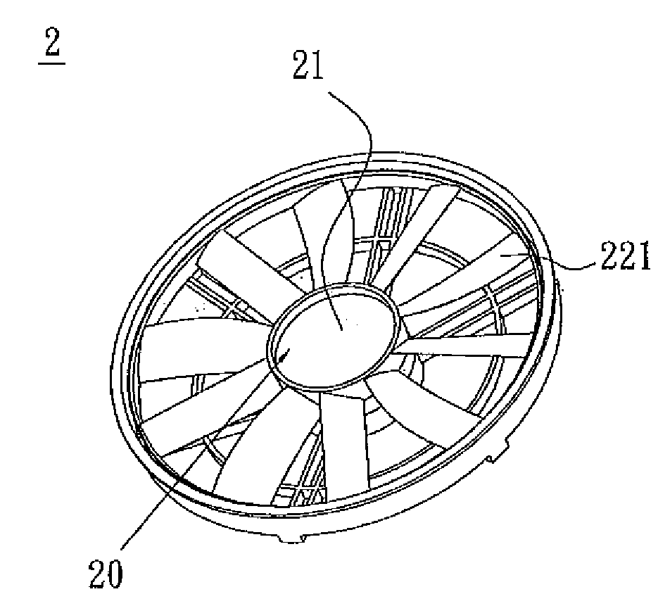
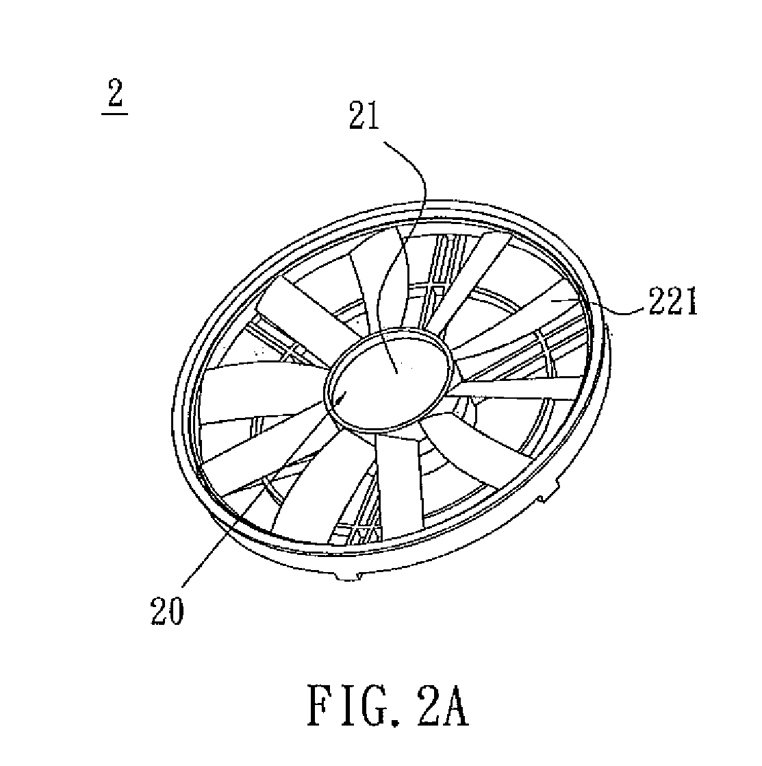
[0024]FIGS. 2A and 2B are the front and back views of a fan 2 according to an embodiment of the present invention. Referring to FIGS. 2A and 2B, the fan 2 includes an impeller 20, a motor 21 and a frame 23. The impeller 20 and the motor 21 are disposed within the frame 23. The motor 21 is connected with the impeller 20 to drive it to rotate. In this embodiment the fan 2 is, for example but not limited to, an axial-flow fan. Of course, the fan of the present invention can be a centrifugal fan as well.

[0025]FIG. 2C shows the impeller 20 in FIG. 2A. With reference to FIGS. 2A and 2C, the impeller 20 includes a hub 21 and an odd number of blade sets 22. The blade sets 22 are disposed around the circumference of the hub 21. Each blade set 22 has at least two blades 221. In this embodiment,...


PUM


Abstract

A fan has an impeller, a motor and a frame. The impeller and the motor are disposed within the frame, and the motor is connected to the impeller and drives the impeller to rotate. The impeller includes a hub and an odd number of blade sets. The blade sets are disposed around the circumference of the hub. Bach blade set has a plurality of the blades, and the blades of each blade set can be the same or not. For example, the blades in each of the blade sets have different tilting angles, heights and / or lengths while the blades are connected with the hub. Or the blades in each of the blade sets have different curvatures, arc lengths, thicknesses, or side-view shapes.

Description

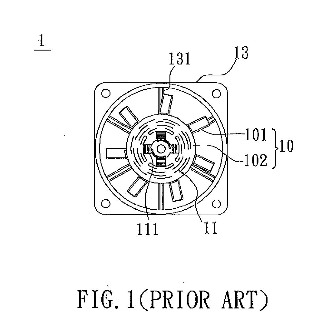
CROSS REFERENCE TO RELATED APPLICATIONS[0001]This Non-provisional application claims priority under 35 U.S.C. §119(a) on Patent Application No(s). 096112018, filed in Taiwan, Republic of China on Apr. 4, 2007, the entire contents of which are hereby incorporated by reference.BACKGROUND OF THE INVENTION[0002]1. Field of Invention[0003]The present invention relates to a fan and an impeller thereof, and in particular to a fan and an impeller thereof with an odd number of blade sets.[0004]2. Related Art[0005]As developments of electronic products with good performance, high operating frequencies, fast speeds and compact sizes, lots of heat and thus high temperature are generated that easily results in instability during their operations and affects the reliabilities of the electronic products. Therefore, heat dissipation has become one important issue in the design of electronic devices.[0006]Fan is a commonly used in heat dissipation. FIG, 1 shows a conventional fan 1. The impeller 10 ...

Claims


Application Information

Patent Timeline
IPC IPC(8): F04D29/18F01D5/14F04D29/40
CPCF04D29/326F04D29/327F04D29/384F04D29/666
Inventor LAN, CHUNG-KAICHEN, HUNG-CHILIN, LI-CHEN
Owner DELTA ELECTRONICS INC
Learn More