Method of creating super-hydrophobic and-or super-hydrophilic surfaces on substrates, and articles created thereby

a technology of super-hydrophobic and/or super-hydrophilic surfaces, which is applied in the direction of instruments, nuclear engineering, transportation and packaging, etc., can solve the problems of many failures of electronic consumer products, limited effectiveness of coating a textured or roughened surface to produce super-hydrophobic behavior, and instantaneous wetting of the surface of such materials

Inactive Publication Date: 2008-10-09
APPLIED MICROSTRUCTURES
View PDF50 Cites 94 Cited by
  • Summary
  • Abstract
  • Description
  • Claims
  • Application Information

AI Technical Summary

Benefits of technology

[0032]One aspect of the present invention pertains to a chemical vapor deposition method of treating and coating materials to provide the desired super-hydrophobic or super-hydrophilic properties. A surface topography is created using a CVD deposition of particles nucleated in situ by reacting two or more vaporous precursors in the gas phase to form nano-particles. The nano-particles are subsequently deposited onto the substrate, forming a rough surface topography. The gas phase reaction processing parameters are controlled so that the size of the resulting surface topography is carefully controlled. As a method of monitoring the effect of various processing parameters on the resulting surface topography, a surface roughness in nanometers RMS (Random Mean Square) is measured by AFM (Atomic Force Microscopy). By varying the process parameters, it was possible to control the RMS from a few up to hundreds of nanometers. The processing parameters which were controlled included the amount of reactants charged to the processing chamber, the relative ratios of reactants, the reaction pressure, time, and temperature, and the number of reaction cycles, by way of example and not by way of limitation.

Problems solved by technology

A super-hydrophilic material is typically characterized by a water contact angle of 0 (zero) degrees, which results in an instantaneous wetting of the surface of such a material.
The effectiveness of coating of a textured or roughened surface to produce a super-hydrophobic behavior is typically limited by adhesion of the super-hydrophobic coating material to the substrate material surface.
Many failures of electronic consumer products are due to corrosion and electric shorts caused by accidental wetting or atmospheric moisture condensation on components and wiring leads of electronic boards.
In addition, spill accidents are statistically responsible for about 20% of all portable electronics replacements.
Marine electronics products and products exposed to wet or humid conditions are particularly vulnerable to such failures.
However, the performance of electronic boards, board interconnects and mounting remain as critical bottlenecks for product reliability.
Therefore, device performance and reliability can be compromised when electronic boards are exposed to liquids or excessive moisture during everyday use.
Environmental contaminants which form ionic solutions in a wet environment can result in leakage or shorts between the device leads.
Corrosion over time can further damage electrical connections and render devices non-operational.
However, due to a relatively high cost of such protective coatings, and other disadvantages such as, for example, poor heat dissipation, only specialty and military use electronics use board level protection in the form of a moisture-resistant coating.
However, the coatings generated are not super hydrophobic in nature.
However, the single or dual layer protective coatings were found to be inadequate in many cases.
Without precise control of the deposition process, the coating may lack thickness uniformity and surface coverage.
The presence of non-uniformities may result in functional discontinuities and defects on the coated substrate surface which are unacceptable for the intended application of the coated substrate.
In the case where there is too much gas phase reaction, the resulting surface roughness becomes too large (RMS is greater than about 100 nm), with the layer of deposited material being very fluffy and not well adhered to the substrate.

Method used


Image

  • Method of creating super-hydrophobic and-or super-hydrophilic surfaces on substrates, and articles created thereby
  • Method of creating super-hydrophobic and-or super-hydrophilic surfaces on substrates, and articles created thereby
  • Method of creating super-hydrophobic and-or super-hydrophilic surfaces on substrates, and articles created thereby

Examples


example one

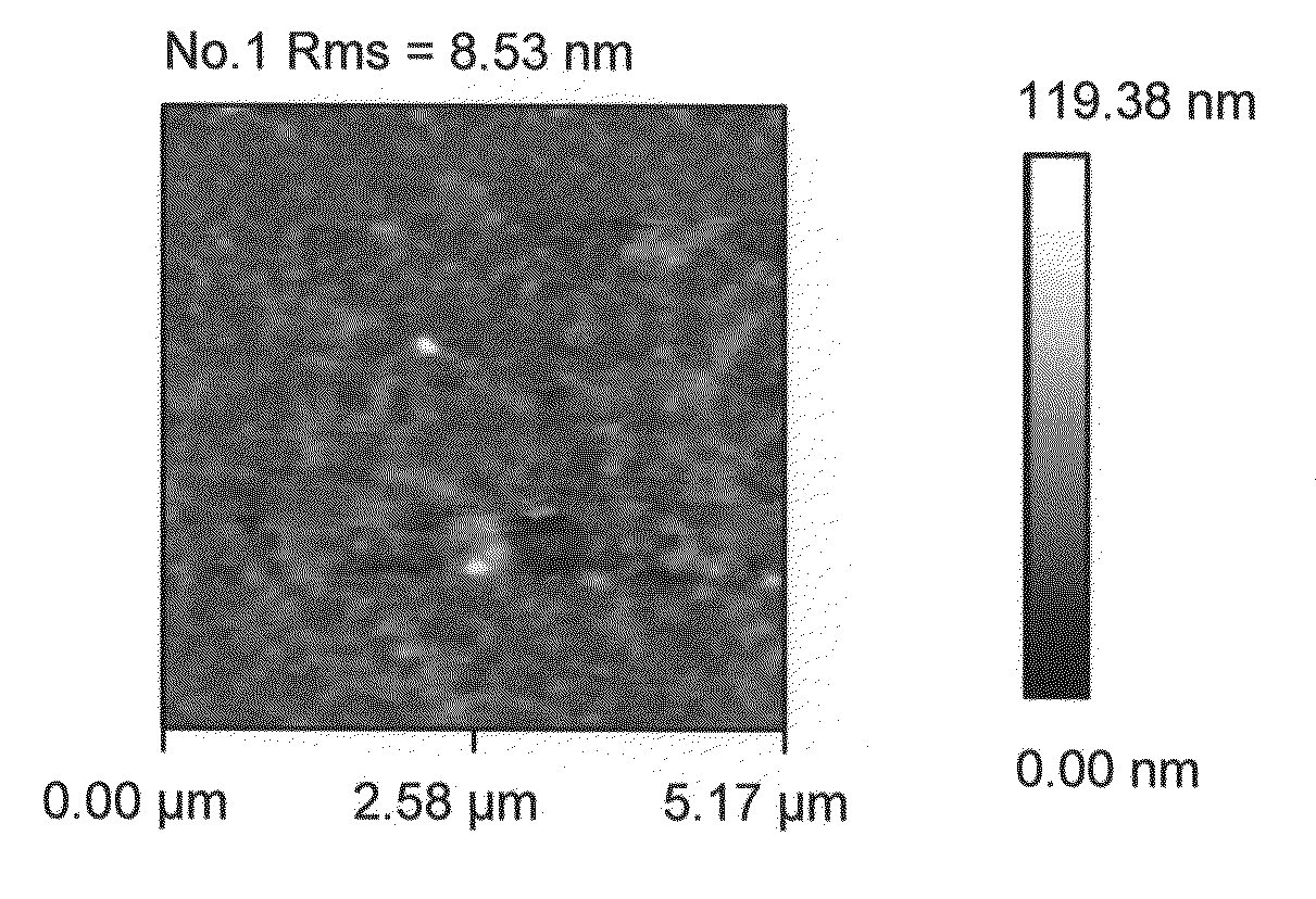
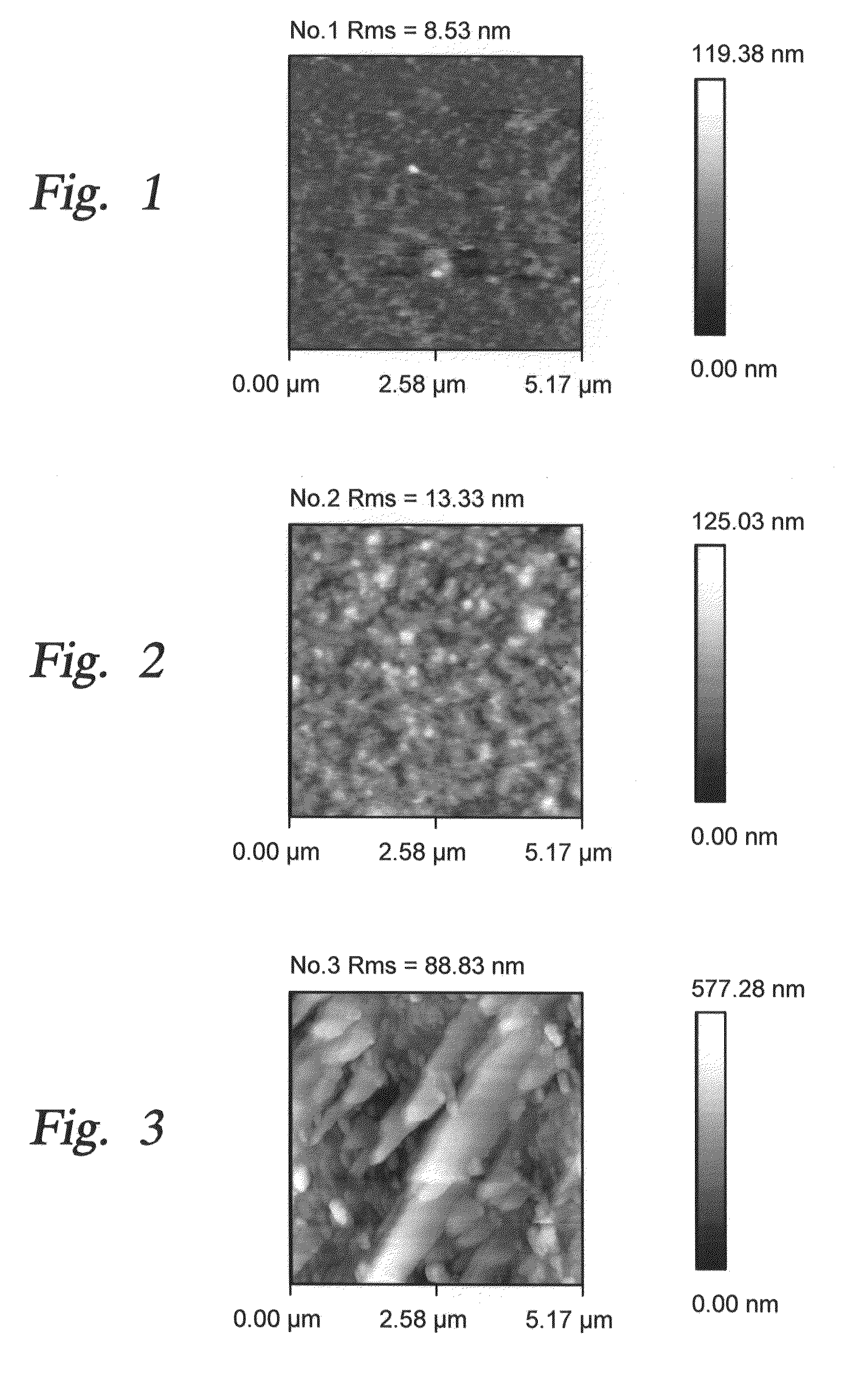
[0051]During current experimentation, we formed rough alumina films in a single step by nucleating alumina nano-particles in a gas phase and depositing them onto a single crystal silicon substrate. In one implementation a CVD reaction of TMA (trimethylaluminum) and water vapor was used. In the past, such spontaneous gas phase reactions were considered to be problematic since they produced undesirable particles due to gas phase nucleation. In the present instance, such a gas phase reaction has been purposely used to form nano-particles. The reaction parameters are selected to control the rate of nano-particle formation and consequently the desired size of the surface roughness features. Examples of the reaction parameters and their impact on surface roughness are shown in the Table One below, where reaction precursors of TMA and Water Vapor were used to produce roughened surfaces. In one instance, a combination of TMA, Water Vapor and perfluorodecyltrichlorosilane (FDTS) reaction pre...

example two

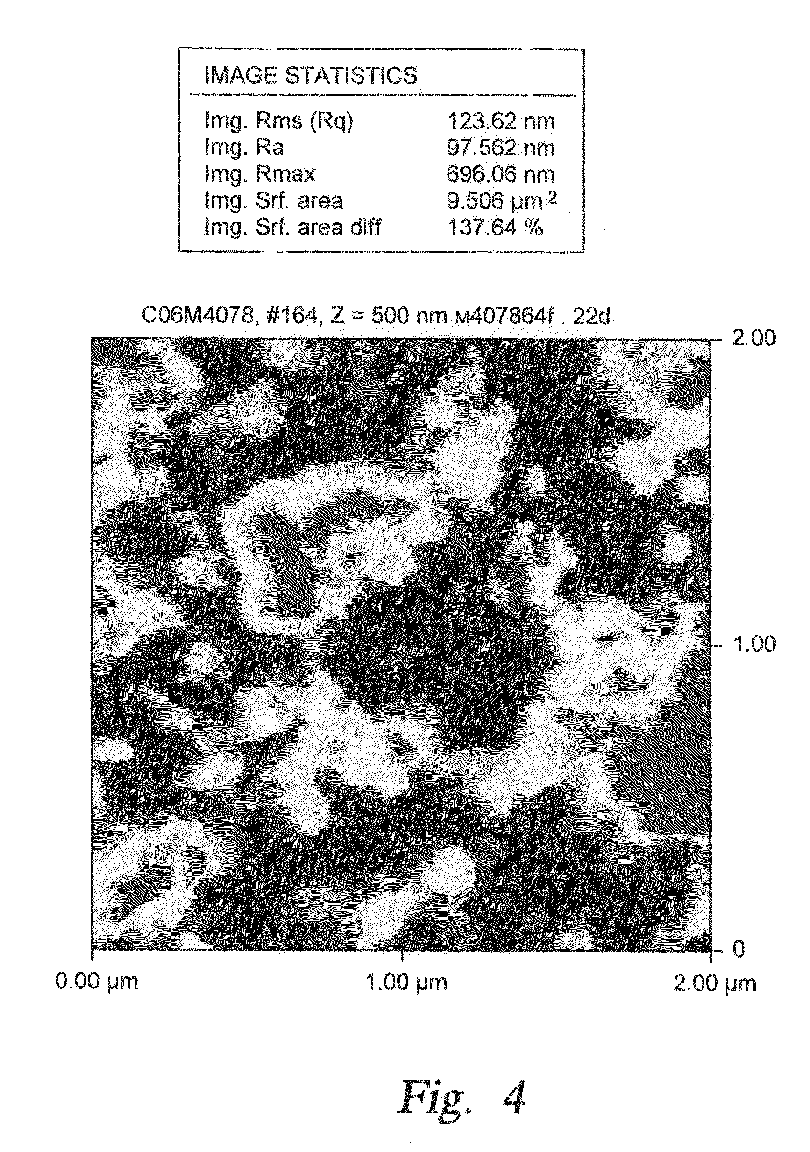
[0062]As discussed above, a single step reaction can be used to form a super-hydrophobic film. A one-step CVD reaction may be carried out, which consists of introducing two highly reactive vapors (TMA and Water) and a fluorocarbon vapor (FDTS) into the reactor under controlled conditions to form hydrophobic nano-particles, and depositing the resulting nano-particles onto a substrate surface to form a super-hydrophobic topographic layer having a water contact angle >150 degrees. It was necessary to adjust the relative precursor partial pressures which were illustrated in Run No. 4 of Table One to obtain a topographic layer which showed lower porosity and better adhesion to the substrate. Recommended reaction precursors and process conditions are as follows: TMA, partial pressure 0.2-2 Torr; Water vapor, partial pressure 2-20 Torr; FDTS, partial pressure, 0.02-0.5 Torr; Reaction temperature, room temperature to 100° C., typically 40-70° C.; Reaction time 5-30 min. This reaction can be...

example three

[0065]A two step reaction may be used to produce a super-hydrophobic film. In this example, a two step CVD reaction was carried out, comprising:

[0066]Step 1) Introducing two highly reactive vapors (TMA and Water) into the reactor under controlled conditions (below) to form hydrophilic nano-particles and depositing the resulting nano-particles onto a substrate surface, followed by

[0067]Step 2) Functionalizing the resulting rough surface with a hydrophobic coating by vapor deposition of a SAM (FDTS, perfluorodecyltrichlorosilane, precursor was used, for example and not by way of limitation).

[0068]Preferred reaction precursors and CVD process conditions for the two step reaction: Step 1): TMA, partial pressure 2-10 Torr; Water, partial pressure 20-60 Torr; Reaction temperature, room temperature to 100° C., typically 40-70° C.; Reaction time 5-30 minutes. Step 2): FDTS, partial pressure 1-2 Torr; Water, partial pressure 5-10 Torr; Reaction temperature, room temperature to 100° C.; typic...


PUM

PropertyMeasurementUnit
surface roughnessaaaaaaaaaa
contact angleaaaaaaaaaa
surface roughnessaaaaaaaaaa

Abstract

The present invention is related to a chemical vapor deposition method of depositing layers of materials to provide super-hydrophilic surface properties, or super-hydrophobic surface properties, or combinations of such properties at various locations on a given surface. The invention also relates to various product applications which make use of super-hydrophobic surface properties, such as electronic devices, biological analytical and diagnostic tools, and optical devices, for example.

Description

[0001]The present application claims priority under Provisional Application Ser. No. 60 / 921,618, filed Apr. 2, 2007, and titled: “CVD Method Of Surface Treatment To Provide Super-Hydrophobic and Super-Hydrophilic Properties”. This provisional application is incorporated by reference herein in its entirety. In addition, the present application is related to a series of patent applications pertaining to the application of thin film coatings on various substrates, particularly including the following applications, each of which is hereby incorporated by reference in its entirety: U.S. application Ser. No. 10 / 759,857, filed Jan. 17, 2004, and titled: Apparatus And Method For Controlled Application Of Reactive Vapors To Produce Thin Films and Coatings; U.S. application Ser. No. 11 / 112,664, filed Apr. 21, 2005, and titled: Controlled Deposition Of Multilayered Coatings Adhered By An Oxide Layer; U.S. application Ser. No. 11 / 295,129, filed Dec. 5, 2005, and titled: Controlled Vapor Deposit...

Claims


Application Information

Patent Timeline
Patent Type & Authority Applications(United States)
IPC IPC(8): B32B33/00C23C16/00C08J7/18C23C14/02
CPCC08J7/16Y10T428/24802C23C16/45514C23C16/403
Inventor KOBRIN, BORIS
Owner APPLIED MICROSTRUCTURES
Why Eureka
Try Eureka