
Wiper System for Front Windscreens of Motor Vehicles

a technology for front windscreens and motor vehicles, applied in the field of windshield wipers, can solve the problems of inability to pierce the front windshield, which is required for this, and is no longer permissible in many modern glass materials, and has adverse effects on surface stability and fracturing behavior

Inactive Publication Date: 2008-10-16
ROBERT BOSCH GMBH
View PDF7 Cites 4 Cited by
  • Summary
  • Abstract
  • Description
  • Claims
  • Application Information

AI Technical Summary

Benefits of technology

[0011]Conventional front windshields are generally of relatively flat design with a small curvature and have small changes of curvature over the entire region to be traversed by the wiper blades. Wiper systems correspondingly designed for use on such windshields guide at least one wiper blade over the windshield, said wiper blade comprising an elastic holder which receives a strip-shaped rubber profile with a lip suitable for drawing over the windshield. The elastic properties of the wiper blade permit small differences between the curvature of the windshield and the curvature of the wiper blade in the relaxed state to be compensated for. In addition to an optimized selection of material and a lip shape matched to the wiper blade and in conjunction with an appropriate orientation of the placed-on lip of the wiper blade with respect to the normal of the windshield zone traversed, this ensures an effective and uniform keeping of the front windshield free from spray and rainwater. In particular, it is endeavored as a rule to arrange the wiper blade in such a manner that, during the drawing-over operation, compressions of the rubber lip are avoided. In the case of wiper systems operating bi-directionally, a corresponding folding over of the lip of the wiper blade generally takes place during the change in direction, which requires a largely perpendicular placing of the wiper blade on the windshield. All of these requirements can advantageously be met with the invention.
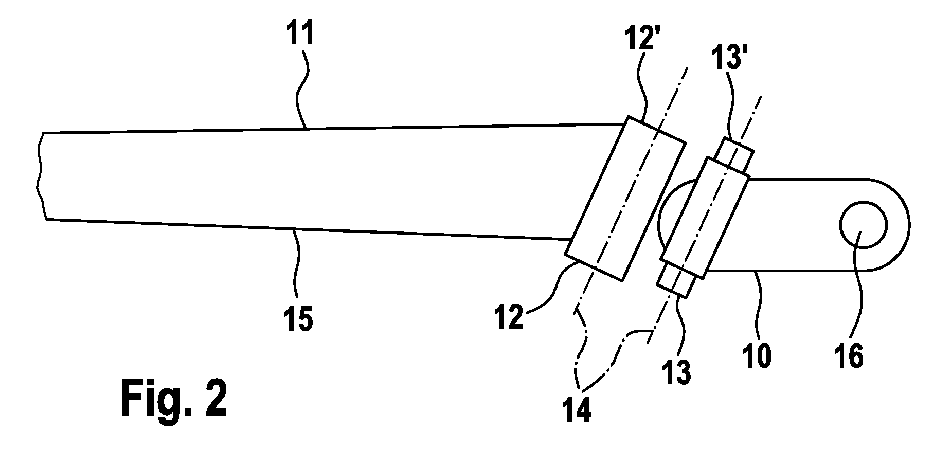
[0019]The use of a single-axis articulation part, the axis of articulation of which deviates from the perpendicular to the main axis of the wiper arm at least in the plane in which the fastening part is pivoted, is advantageous.
[0022]When a wiper system according to the invention is used on wraparound windshields with a gently curved central region and sharply curved border regions, it is particularly advantageous if the wiper blade can be moved between a steep end position in the sharply curved border region of the wraparound windshield and a flat end position in the central, more gently curved region of the wraparound windshield. In the case of systems of this type with external mounting, the pivot axis may be arranged in such a manner that a significant change in the angle between the wiper arm and the fastening part arises only when a wiper blade is at a relatively steep angle. As a result, the wiper blade traverses the relatively gently curved central region of the wraparound windshield with the wiper lip at a virtually constant approach angle. Only when the wiper blade is at a steeper angle does a significant turning-in according to the invention of the wiper blade take place, which permits adaptation of the movement to the more sharply curved border region of the wraparound windshield. As a result, sharp differences in curvature do not have to be compensated for by an elastic deformation of the wiper blade, and a uniform contact pressure over the entire length of the wiper blade can be realized independently of the curvature.

Problems solved by technology

However, this solution has the disadvantage that a piercing, which is required for this, of the front windshield is no longer permissible in many modern glass materials used for front windshields.
Such a measure, which has an adverse effect on the surface stability and the fracturing behavior, is impermissible in particular in the case of frequently used laminated glass.

Method used


Image

  • Wiper System for Front Windscreens of Motor Vehicles
  • Wiper System for Front Windscreens of Motor Vehicles
  • Wiper System for Front Windscreens of Motor Vehicles

Examples


Embodiment Construction

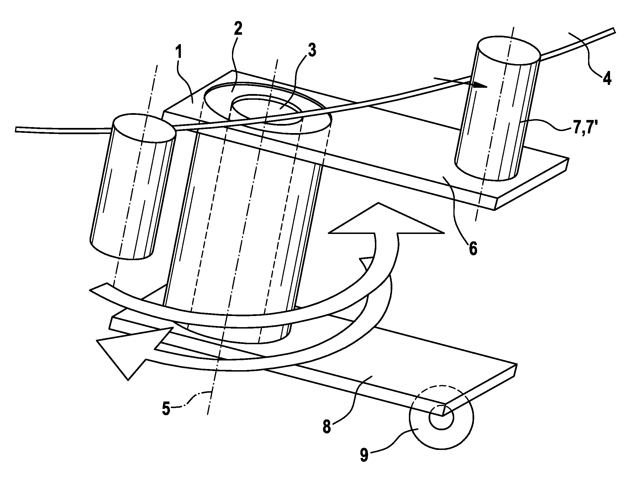
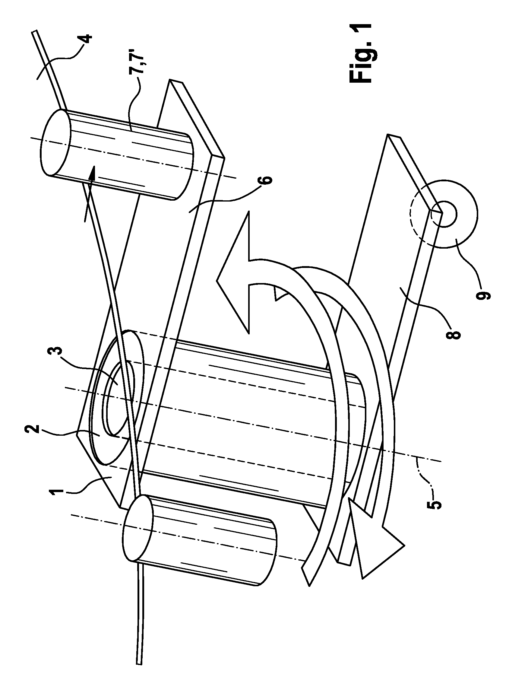
[0028]FIG. 1 shows a schematic illustration of a bearing part 1 according to the invention. A bearing bushing 2 is pushed onto a bearing shaft 3 which is arranged in the vehicle interior in a positionally fixed manner below a front windshield 4 which is designed as a wraparound windshield. The bearing shaft 3 determines the position of the axis 5 about which the bearing part 1 can be pivoted. The bearing part 1 furthermore comprises a support 6 which is connected fixedly to the bearing bushing and on which a bolt-shaped bearing shaft 7 is fastened as the fastening means at a fixed distance from the bearing bushing 2. Said bearing shaft 7 serves to receive a fastening part which can be connected at this point to the bearing part 1 in a manner secure against rotation. The bearing bushing 2 ensures a pivotable arrangement of the bearing part 1 on the bearing shaft 3.

[0029]A spatial separation of the pivot axis 5, about which the bearing part and therefore the wiper arrangement is pivot...


PUM


Abstract

The invention relates to a wiper system for the front windscreens of motor vehicles. Said system comprises at least one wiper blade, which can be guided over the front windscreen (4) on a pivotable wiper arm (11), at least one bearing part (1) that can be pivoted about an axis (5), at least one fixing part (10) that can be connected to the bearing part (1) in a non-torsional manner and at least one single-axis articulation that connects the wiper arm (11) to the fixing part (10). The position of the connection between the bearing part (1) and fixing part (10) lies in the vicinity of the axis (5) about which the bearing part (1) is pivoted.

Description

BACKGROUND OF THE INVENTION[0001]The invention relates to a wiper system for front windshields of motor vehicles.[0002]Wiper systems serve to maintain a free view in the event of a spontaneously occurring action upon vehicle windshields with sight-obstructing substances, in particular in the event of precipitation-induced sight obstructions due to adverse weather conditions.[0003]Front windshields with enhanced functionality are increasingly found in modern motor vehicles. That is to say, in addition to ensuring that the driver has an unobstructed view, modern front windshields have to satisfy further functions relevant to safety, from mechanical occupant protection to static incorporation in strength calculations of bodywork and passenger compartment. This leads, firstly, to changes in the front windshield geometry and size and, secondly, to changes in the front windshield material in order to be able to satisfy the increased safety and strength requirements.[0004]As a result of no...

Claims


Application Information

Patent Timeline
IPC IPC(8): B60S1/04
CPCB60S1/3409B60S1/345B60S1/3495B60S1/34
Inventor ESCHENBRENNER, NICOLASSCHABANEL, FRANCOIS
Owner ROBERT BOSCH GMBH
Learn More