Dynamic verification method for a riveting process with blind rivets carried out with an automatic riveting apparatus, and verifying device for carrying out the verification

a technology of automatic riveting and dynamic verification, which is applied in the direction of metal-working machine components, manufacturing tools, and shape safety devices, etc., can solve the problems of not being able to use hi-lock type, not being able to gain access, and not knowing whether the rivet has been placed correctly

Inactive Publication Date: 2008-10-16
AIRBUS OPERATIONS SL
View PDF9 Cites 23 Cited by
  • Summary
  • Abstract
  • Description
  • Claims
  • Application Information

AI Technical Summary

Problems solved by technology

The problem associated with the manufacture of structures closed with pieces joined by riveting, for example torsion boxes introduced in the structure, is well known, since it is not possible to use hi-lock type (nut and bolt) rivets due to the fact that the rear parts of the riveted pieces are not accessible.
The problem existing in the use of blind rivets lies in, among other things, the fact that once the rivet has been attached, there is no possibility of gaining access in order to inspect whether the free end part of the rivet has really trapped the head of the stem correctly or not, and therefore of not knowing whether the rivet has been placed correctly or not.
Nevertheless, these rivets are relatively costly and their reliability in terms of the possibility of detecting the incorrect placing of a rivet is less than desirable.

Method used


Image

  • Dynamic verification method for a riveting process with blind rivets carried out with an automatic riveting apparatus, and verifying device for carrying out the verification
  • Dynamic verification method for a riveting process with blind rivets carried out with an automatic riveting apparatus, and verifying device for carrying out the verification
  • Dynamic verification method for a riveting process with blind rivets carried out with an automatic riveting apparatus, and verifying device for carrying out the verification

Examples


first embodiment

[0124]FIG. 6 illustrates the assignment table 7 contained in the memory 6a, in which

[0125]an initial type value of displacement (ab1) is assigned to an initial type value of traction force (aa1) applied in an initial type stage (a),

[0126]a plurality of consecutive intermediate type values (bb1-bbn) are assigned to respective consecutive intermediate type values of traction force (ba1-ban) consecutively applied in the intermediate type stage (B);

[0127]a terminal type value of displacement (cb1) is assigned to a terminal type value of traction force (ca1).

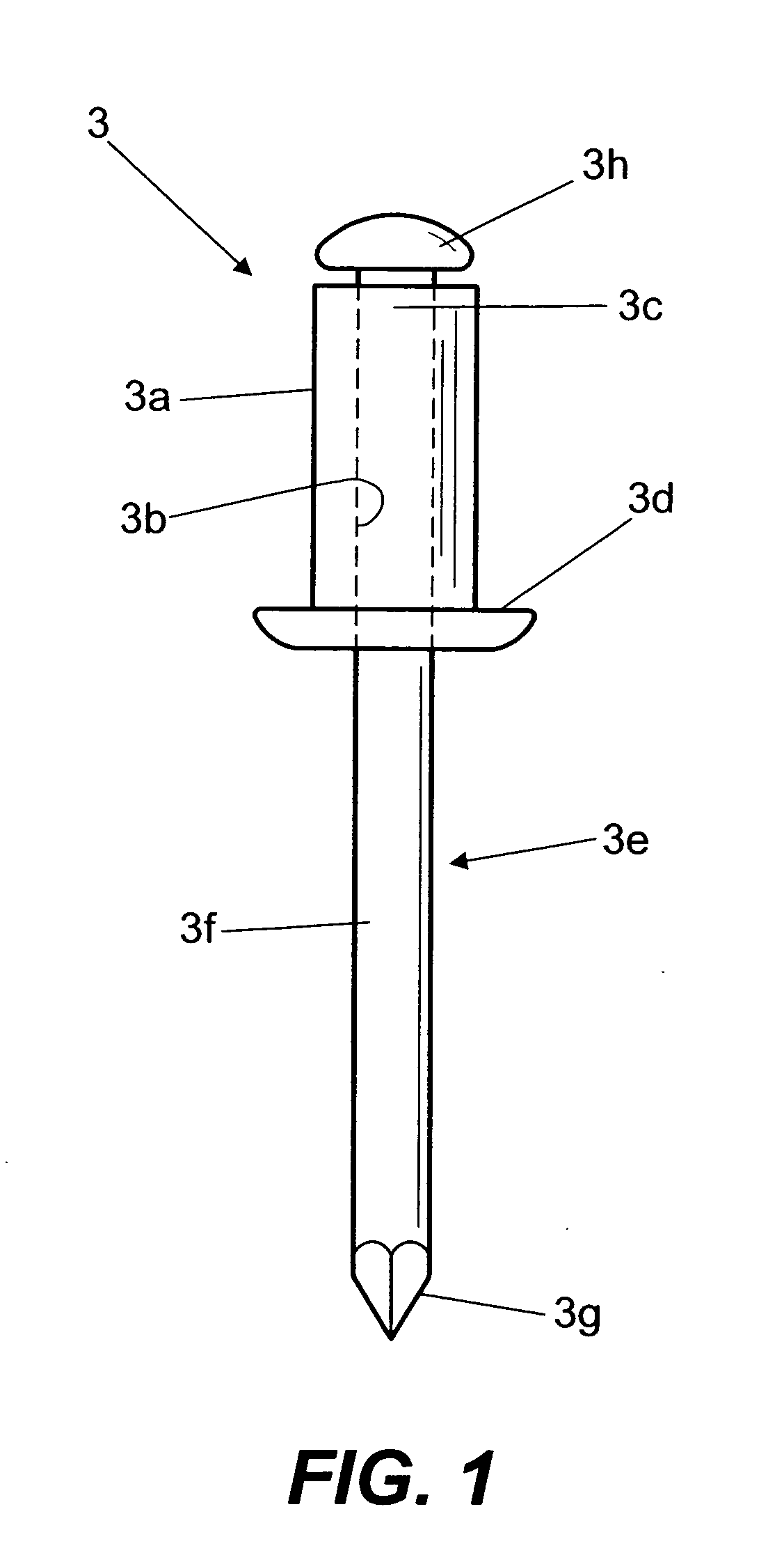
[0128]The type values (aa1, ab1, ba1-ban, bb1-bbn, ca1, cb1) correspond to a type riveting corresponding to the riveting carried out with a standard blind rivet corresponding to the blind rivet 3 which is applied by means of a standard riveting apparatus corresponding to the riveting apparatus 1 that is used.

[0129]The processing means include controlling means 6b, for example in the form of a control programme, which, via the electri...

second embodiment

[0134]FIG. 7 illustrates the assignment table 7 contained in the memory 6, which includes,

[0135]with respect to the initial type value of displacement (ab1) of the stem 3a of the blind rivet 3 with respect to its body 3a, an initial type value of minimum displacement (ab1-min) and an initial type value of maximum displacement (ab1-max) which define an acceptable initial interval (ac) of initial type values of displacement, and also, with respect to each initial type value of traction force (aa1), an initial type value of minimum traction force (aa1-min) and an initial type value of maximum traction force (aa1-max) which define an acceptable initial interval (ad) of initial type values of traction force;

[0136]with respect to each intermediate type value of displacement (bb1-bbn) of the stem 3a of the blind rivet 3 with respect to its body 3a, an intermediate type value of minimum displacement (bb1(min)-bbn(min)) and an intermediate type value of maximum displacement (bb1(max)-bbn(max...


PUM

PropertyMeasurementUnit
traction forceaaaaaaaaaa
displacementaaaaaaaaaa
traction forcesaaaaaaaaaa

Abstract

A method and device are provided for verification of the quality of placing of blind rivets. The verification method involves successively carrying out, during the application of traction force to a stem, initial measurements in an initial state of the application of the traction force to obtain an initial traction force and an initial displacement of the rivet stem relative to the rivet body, intermediate measurements in an intermediate stage of the application of the traction force to obtain an intermediate traction force and an intermediate displacement, and terminal measurements in a terminal stage of the application of the traction force to obtain a terminal traction force and a terminal displacement. The obtained values are compared to acceptable values in an assignment table.

Description

TECHNICAL FIELD OF THE INVENTION[0001]The present invention belongs to the field of riveting technology for blind rivets and is particularly applicable to the sector of automatic riveting stations which requires great precision and reliability in the riveting finishings, such as for example the aeronautical industry.PRIOR ART OF THE INVENTION[0002]The problem associated with the manufacture of structures closed with pieces joined by riveting, for example torsion boxes introduced in the structure, is well known, since it is not possible to use hi-lock type (nut and bolt) rivets due to the fact that the rear parts of the riveted pieces are not accessible. Therefore, in order to rivet this type of structure one usually uses blind rivets which only need access from one side in order to be applied.[0003]A blind rivet consists of a body with an interior passage, a deformable free end part and an end part with a rivet head in the form of a collar, together with a stem displaceable in said ...

Claims


Application Information

Patent Timeline
Patent Type & Authority Applications(United States)
IPC IPC(8): B21C51/00B21J15/02
CPCB21J15/043B21J15/10B21J15/285Y10T29/53743Y10T29/53739Y10T29/49776Y10T29/4978Y10T29/49771Y10T29/49956Y10T29/53748
Inventor SANCHEZ-BRUNETE ALVAREZ, DESIDERIO
Owner AIRBUS OPERATIONS SL
Why Eureka
Try Eureka