Solar Panel Array Sun Tracking System

a solar panel array and tracking system technology, applied in the field of solar energy collection, can solve the problems of complex installation and commissioning of large solar panel array tracking systems using such drive mechanisms, inability to design the drive mechanism in the prior art, and inability to rotate large arrays in a single drive system, so as to reduce the cost of installation and commissioning, reduce the side load, and reduce the effect of for

Inactive Publication Date: 2008-10-16
THOMPSON TECH IND
View PDF7 Cites 72 Cited by
  • Summary
  • Abstract
  • Description
  • Claims
  • Application Information

AI Technical Summary

Benefits of technology

[0022]Another object is to provide a solar tracking system that eliminates the large side loads typically produced by ram driven systems for large arrays.
[0023]Still another object is to provide a solar tracking system that rotates large arrays cost effectively and with much less force requi...

Problems solved by technology

However, most of the drive mechanisms in the prior art have not been designed to use a single drive unit to move large arrays with multiple rows of panels.
Although numerous panel movement mechanisms have been employed, they are generally ill-suited for using a single drive system to rotate large arrays (i.e., those having 1000 or more panels).
Accordingly, the installation and commissioning of large solar panel array tracking systems using such drive mechanisms have been complicated and therefore costly.
Consequently, the side forces on the panels due to wind loading create substantial torsional forces that must be withstood by the rotational drive mechanism, and this leads to a need for much higher drive forces.
The disadvantage of this approach is that the torque tube and the bearings at the support posts must be quite large to transmit the torque.
The problem with this approach is that the ram force required to drive a large number of panels creates a substantial side force at the ram base.
Another liability of prior art drive systems ...

Method used


Image

  • Solar Panel Array Sun Tracking System
  • Solar Panel Array Sun Tracking System
  • Solar Panel Array Sun Tracking System

Examples


Embodiment Construction

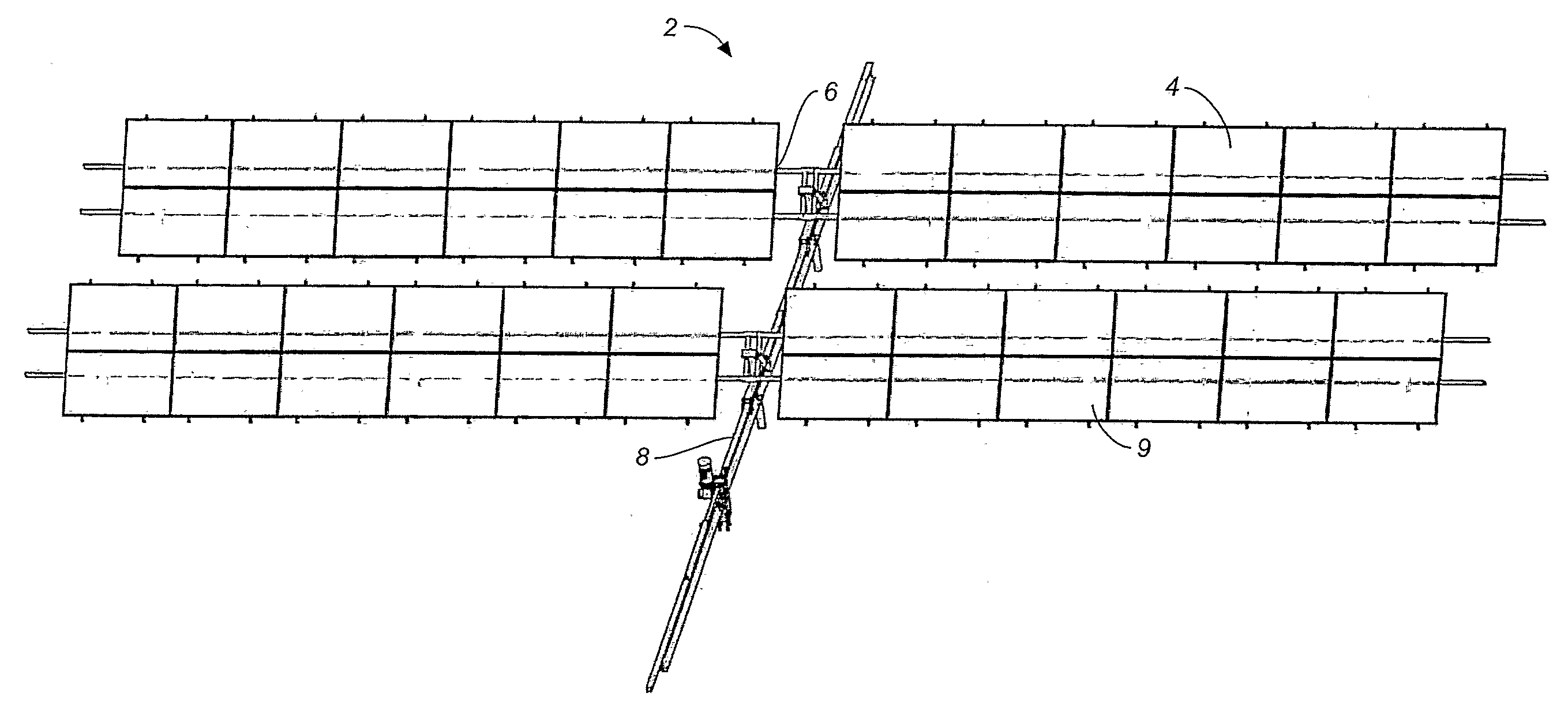
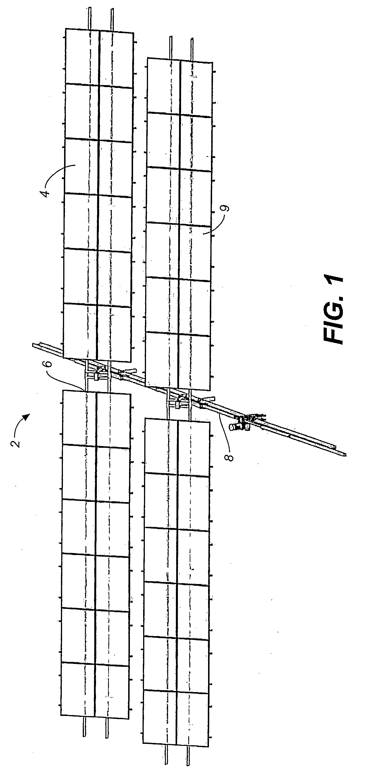
[0091]Referring to FIGS. 1 through 7B, there is illustrated a new and improved solar power sun tracking system. FIG. 1 shows a first preferred embodiment of the solar tracking system of the present invention. The solar panel array 2 generally includes one or more rows of solar panels 4 mounted on a rotatable support structure 6 positioned with a rotation axis A for each panel oriented north and south. The drive system 8 is positioned on an east west axis perpendicular to the rotation axes of the solar panels in the array rows.

[0092]The solar panels in the array are disposed in the same pattern on each side of the of the drive system. This array pattern is repeated for additional rows north and south of the initial row. A series of support posts 9, which in general consists of vertical pilings driven into the ground and related connection hardware are typically used for the support of the array 2.

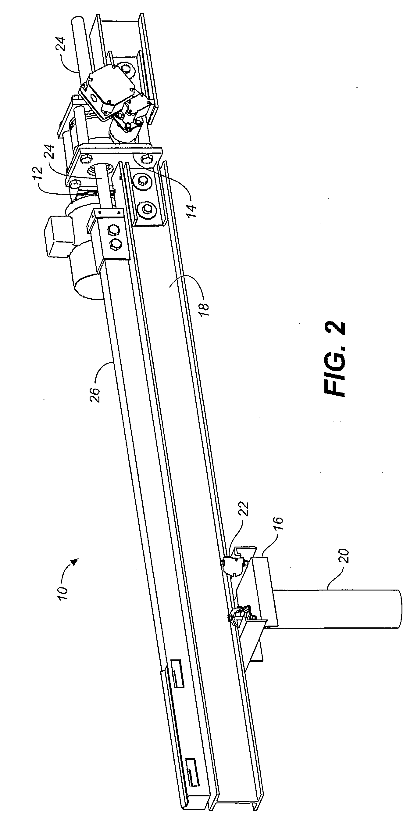
[0093]FIG. 2 shows a preferred drive system 10 for the solar panel array tracking system...


PUM


Abstract

A solar panel tracking system that can simultaneously rotate large arrays of solar panels position in multiple rows utilizing a single drive system. The drive system comprises a single actuation device that drives multiple rotational translation stages at each solar array row for tilting the panels to the correct position. A dual beam structure within each row insure appropriate panel support during rotation and provide the framework for simplified installation and maintenance.

Description

BACKGROUND OF THE INVENTION[0001]1. Technical Field[0002]This invention relates generally to the collection of solar energy for conversion into electrical energy, and more specifically to the arrangement of solar panel drive and tilt mechanisms to follow the movement of the sun relative to the earth. Still more specifically, the present invention relates to a drive mechanism for rotating a large array of solar panels in a cost effective manner.[0003]2. Background Art[0004]For years drive mechanisms have been employed to rotate and align solar panel arrays. However, most of the drive mechanisms in the prior art have not been designed to use a single drive unit to move large arrays with multiple rows of panels. Extremely large multi-megawatt solar power stations are now being planned and built, so the need for efficiently driving large arrays has become an important and necessary part of the solar power system.[0005]In general, solar photovoltaic panels for large scale energy producti...

Claims


Application Information

Patent Timeline
IPC IPC(8): H01L31/042F24S50/20
CPCF24J2/541F24J2002/5451F24J2002/5468F24J2002/5475H02S20/00Y02E10/50F24J2/5232F24J2/5264Y02E10/47H02S20/32F24S30/425F24S25/12F24S2030/14F24S2030/131F24S25/70F24S2030/136
Inventor THOMPSON, DANIEL S.MULLINS, MONTYSTAGER, CRAIGZANTE, ANTHONY
Owner THOMPSON TECH IND
Why Eureka
Try Eureka