Plasma Treatment Apparatus

a technology of treatment apparatus and plasma, which is applied in the direction of chemical vapor deposition coating, transportation and packaging, coating, etc., can solve the problems of easy breakage of guide members at the bolted portions, abnormal discharges are likely to occur, and malfunctions, so as to prevent abnormal discharges

Active Publication Date: 2008-10-16
PANASONIC CORP
View PDF4 Cites 2 Cited by
  • Summary
  • Abstract
  • Description
  • Claims
  • Application Information

AI Technical Summary

Benefits of technology

[0009]According to the invention, as a guide mechanism for guiding the side end surfaces of the substrate on the substrate mounting portion whose upper surface is covered with the ceramic, the both end portions of the bar-shaped ceramic-made guide members arranged on the substrate mounting portion in a plurality of rows in the substrate transporting direction are supported by the supporting members. The arrangemen

Problems solved by technology

Since the resin substrate is thin and deflectable, the resin substrate has a characteristic that a gap can possibly be formed between the resin substrate and the electrode with the resin substrate mounted thereon, so that a malfunction such as an abnormal discharge is likely to occur.
However, in the plasma treatment apparatus having the arrangement in which the upper surface of the electrode is thus covered with the ceramic, if the substrate guide mechanism such as the one described above is adopted, the following malfunction is encountered.
Namely, if a ceramic guide body is attached by bolting on each such occasion, since the ceramic is an extremely brittle and a b

Method used


Image

  • Plasma Treatment Apparatus
  • Plasma Treatment Apparatus
  • Plasma Treatment Apparatus

Examples


Embodiment Construction

[0018]Next, a description will be given of an embodiment of the invention with reference to the drawings.

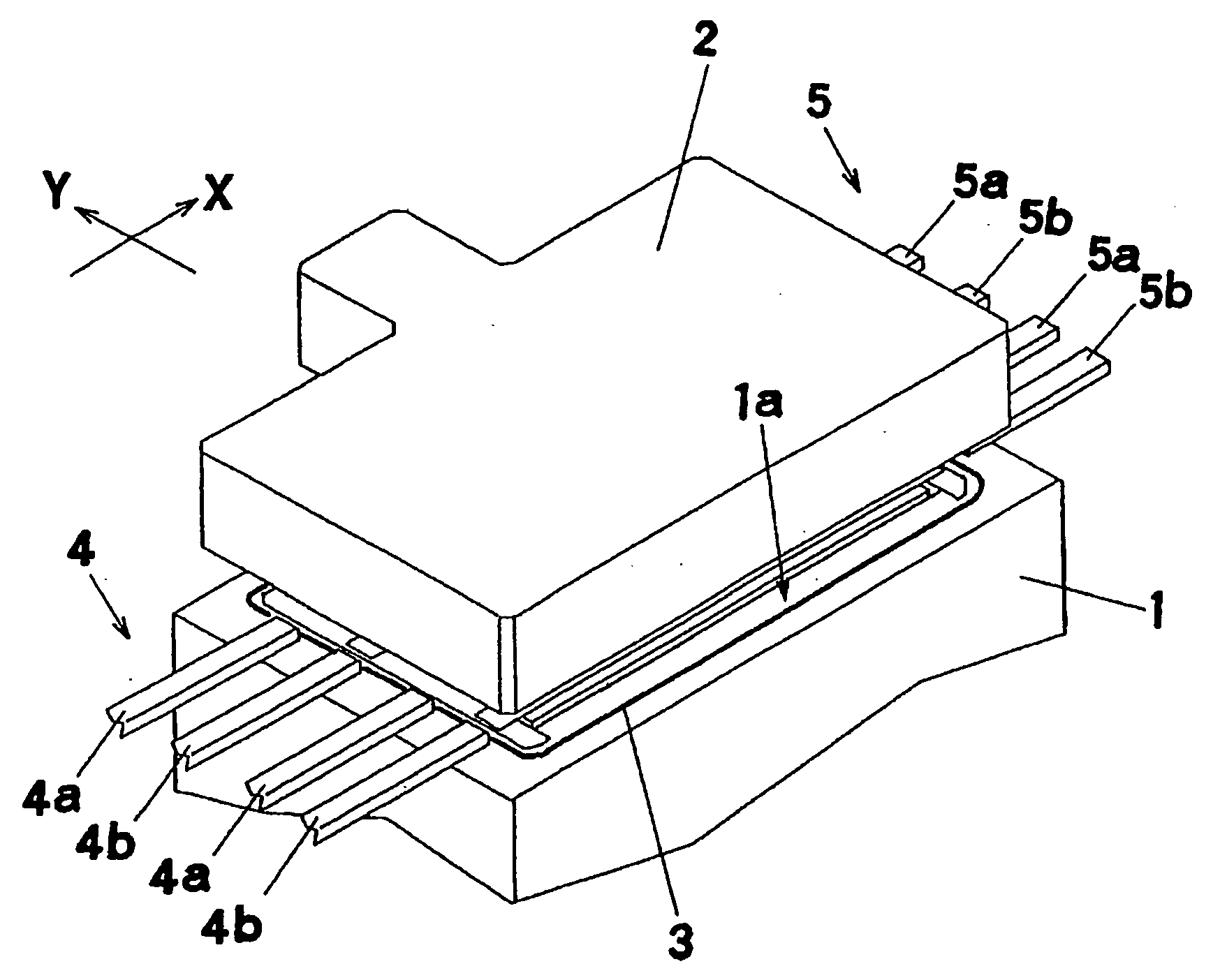
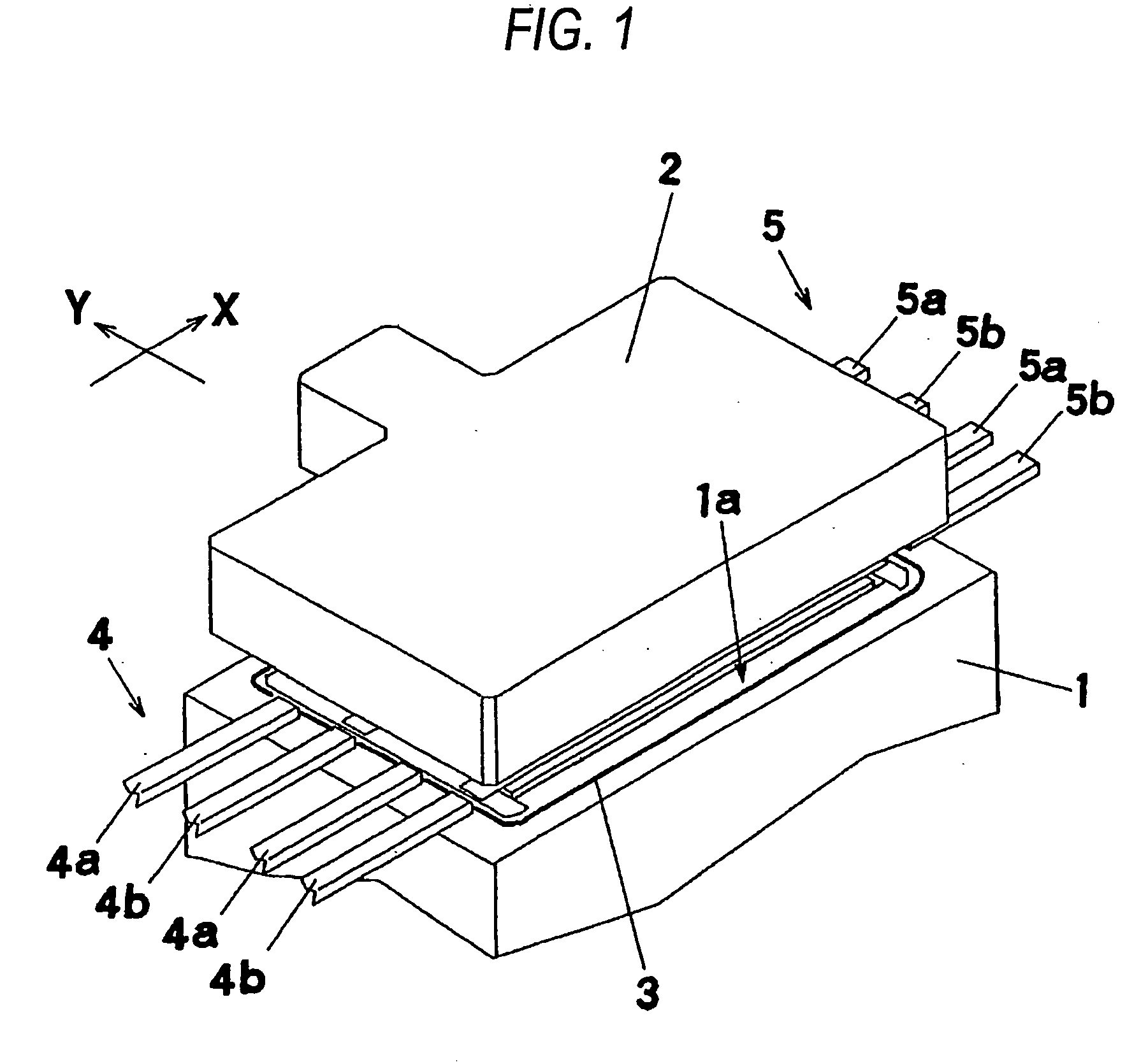
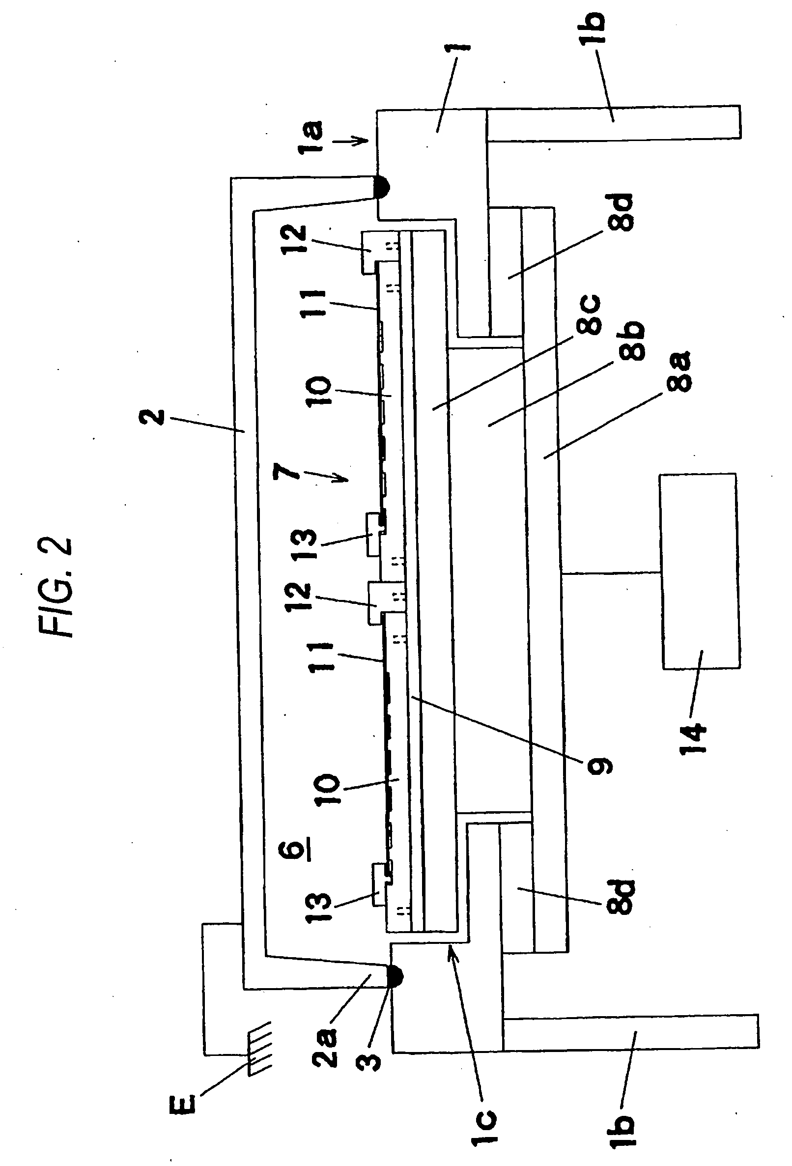
[0019]First, a description will be given of the structure of the plasma treatment apparatus with reference to FIGS. 1, 2, and 3. In FIG. 1, a cover member 2 is disposed above a base portion 1 in such a manner as to be capable of being raised or lowered by a raising / lowering mechanism (not shown). The cover member 2 is a box-shaped member with its lower surface side open, and as the cover member 2 is lowered, and a lower end portion 2a abuts against a base surface 1a on top of the base portion 1, a treatment chamber 6 for plasma treatment is formed. Namely, the base portion 1 forms a bottom portion of the treatment chamber, and the substrate subject to treatment is accommodated in the treatment chamber 6 to effect the plasma treatment of the surface of this substrate. A seal member 3 is fitted to a portion of the base surface 1a where the lower end portion 2a abuts, and as the abu...


PUM

PropertyMeasurementUnit
Currentaaaaaaaaaa
Digital informationaaaaaaaaaa
Dimensionaaaaaaaaaa

Abstract

In a plasma treatment apparatus for performing plasma treatment by accommodating a substrate (11) in a treatment chamber (6), a fixed guide (12) and a movable guide (13) made of a ceramic are arrayed in an X direction (in a substrate transporting direction) for guiding both side end portions of the substrate held on a ceramic-made mounting plate (10), and both end portions of the movable guide (13) are supported by supporting members (18). In this construction, these supporting members (18) are fitted to fixed members (15A) and (15B) arranged in a Y direction with the mounting plate (10) placed therebetween, such that an interval in the Y direction is adjustable. Consequently, the ceramic-made guide member (13) can be mounted and demounted without directly bolting it, and it is possible to prevent the generation of an abnormal discharge by using as objects multiple product thin-type substrates (11) with different widthwise dimensions.

Description

TECHNICAL FIELD[0001]The present invention relates to a plasma treatment apparatus for performing plasma treatment by using a substrate as an object.BACKGROUND ART[0002]Plasma treatment is known as a surface treatment method such as the cleaning and etching of a substrate on which electronic parts are mounted. In this plasma treatment, surface treatment such as cleaning is carried out by the etching action of plasma which is generated by mounting a substrate in a treatment chamber in a reduced-pressure atmosphere and by causing plasma discharge to take place in the treatment chamber. A substrate guide mechanism is provided for guiding the substrate during its carrying-in and carrying-out and for holding the substrate in a proper position and attitude during plasma treatment (e.g., refer to Japanese patent publications JP-A-10-140376 and JP-A-10-223725).[0003]In JP-A-10-140376, a side end surface of the substrate is guided by a bar-shaped guide member arranged in a substrate transpor...

Claims


Application Information

Patent Timeline
IPC IPC(8): C23F1/00
CPCH01J37/32752H01L21/67069H01L21/3065H01L21/68714H01L21/6875Y10S414/141
Inventor KORENAGA, TETSUONAGADOME, RYUJI
Owner PANASONIC CORP
Why Eureka
Try Eureka