Cooling Structure For Batteries and Electrical Units

a technology of cooling structure and battery, applied in the direction of process and machine control, instrumentation, etc., can solve the problems of significant influence of temperature on the output performance of the battery of the battery of the battery, the imbalance of the temperature of each of the batteries in the width direction of the vehicle, and the limitation of a space where the battery is contained in the form of a group. to achieve the effect of reducing electric power

Inactive Publication Date: 2008-10-16
HONDA MOTOR CO LTD
View PDF5 Cites 67 Cited by
  • Summary
  • Abstract
  • Description
  • Claims
  • Application Information

AI Technical Summary

Benefits of technology

[0019]In this case, when the electrical units need to be cooled, it is possible to cool the batteries by driving the cooling fans of the battery boxes while controlling so that the temperature difference between the batteries is kept in a predetermined range, and is possible to cool the electrical units provided on the downstream side. As a result, it is possible to minimize electric power used to drive the cooling fans.

Problems solved by technology

In particular, the output performance of the battery of them significantly is affected by temperature.
However, there have been the following problems in the related art.
That is, as a voltage of an electric power source trends to be increased in the above-mentioned various vehicles, there has been a limitation on a space where the battery is contained in the form of a group.
When the plurality of batteries connected to one another in series is divided and disposed, for example, in a width direction of the vehicle, temperature of each of the batteries becomes imbalanced in the width direction of the vehicle.
For this reason, there are problems in that it is difficult to equally charge the batteries or it is not possible to obtain sufficient output.
As a result, it is not possible to sufficiently charge the batteries.
For this reason, it is difficult to equally charge the batteries on the left and right sides.
As a result, it is not possible to ensure sufficient output of the batteries.
However, since the cooling fan should be provided at each of the equipments in this case, there is a problem in that the weight and cost are increased.

Method used


Image

  • Cooling Structure For Batteries and Electrical Units
  • Cooling Structure For Batteries and Electrical Units
  • Cooling Structure For Batteries and Electrical Units

Examples


Embodiment Construction

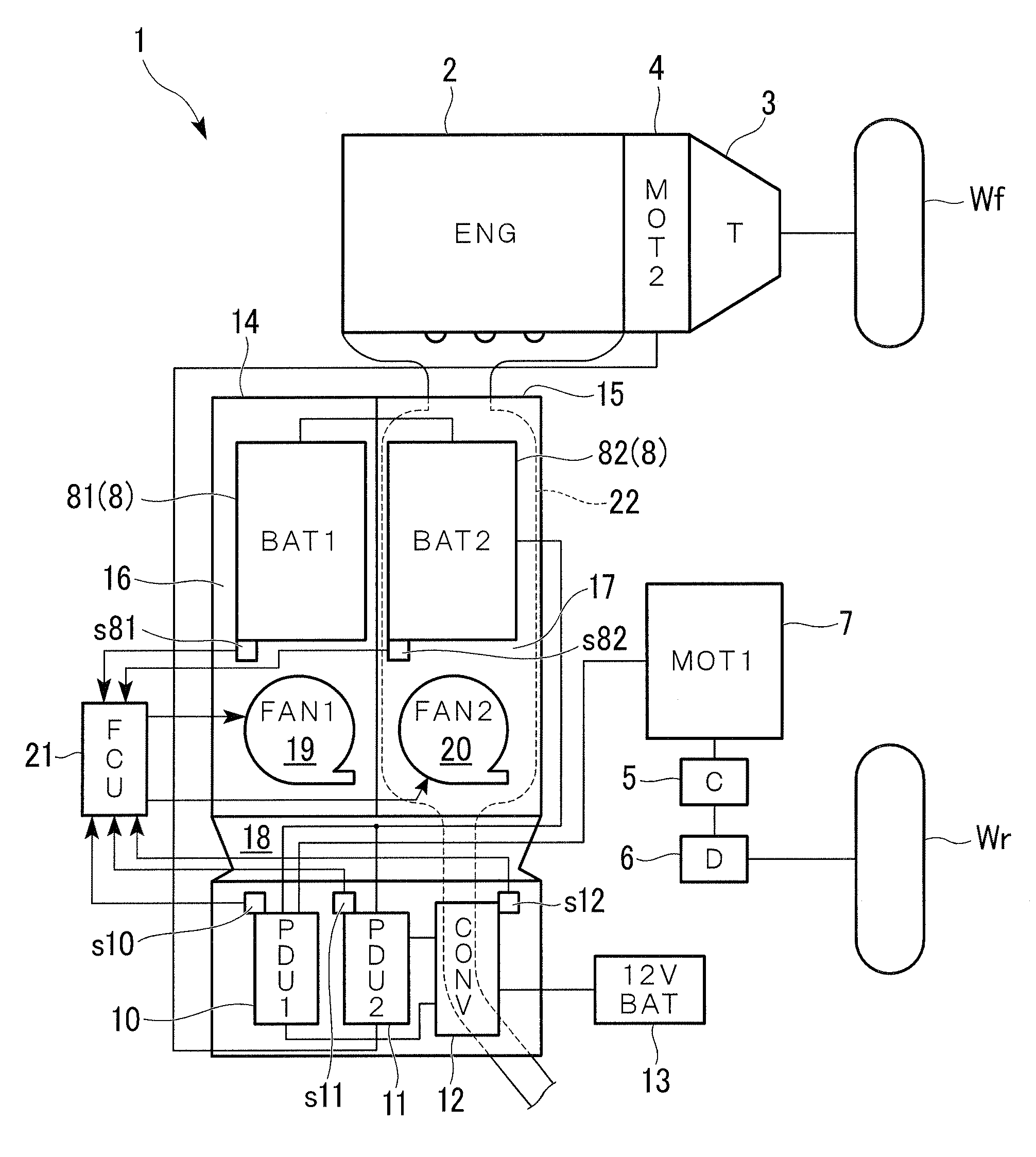
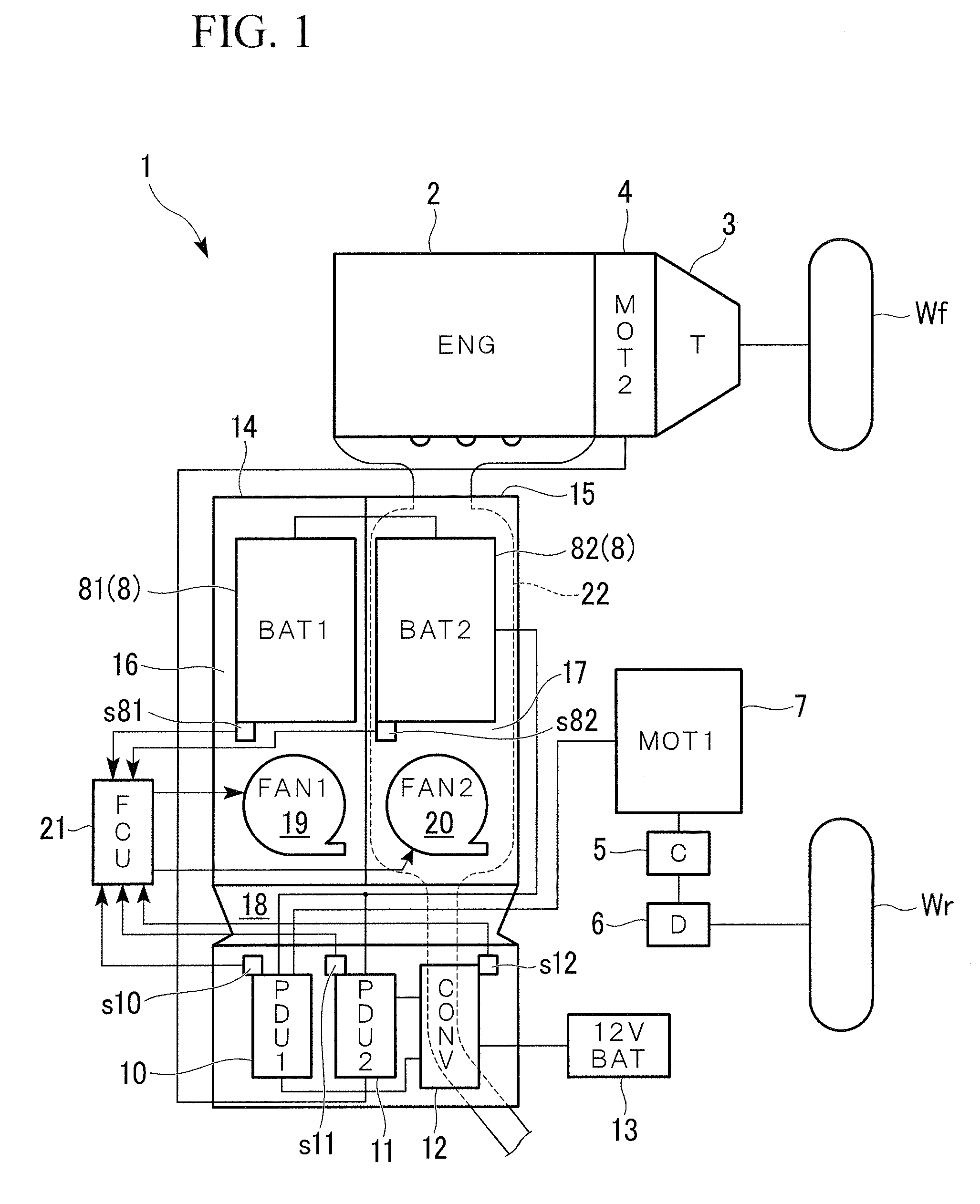
[0030]A preferred embodiment of the present invention will be described below with reference to the drawings. As shown in FIG. 1, a cooling structure for batteries and electrical units according to this embodiment is mounted in a hybrid vehicle 1 that is an example of a vehicle capable of traveling using a driving force generated by a motor.

[0031]The hybrid vehicle 1 is a four-wheel-drive vehicle. A second motor (MOT2) 4 is provided between an engine (ENG) 2 and a transmission (T) 3. Front wheels Wf are connected to the transmission 3 by a clutch (not shown). A first motor (MOT1) 7 is connected to rear wheels Wr by a starting clutch (C) 5 and a differential (D) 6. The two motors 7 and 4 are driven by a high-voltage battery (BAT) 8 and generate driving forces. Further, the two motors 7 and 4 function as generators depending on traveling conditions, and can charge the high-voltage battery 8. Meanwhile, the transmission T may be an automatic transmission.

[0032]The first motor 7 is driv...


PUM

PropertyMeasurementUnit
voltageaaaaaaaaaa
temperature T81aaaaaaaaaa
flow rateaaaaaaaaaa

Abstract

A cooling structure for batteries and electrical units, that cools the batteries being driving sources of a motor mounted in a vehicle capable of traveling by a driving force of the motor and electrical units for driving the motor, the cooling structure including: a plurality of battery boxes that each contain one of the batteries; cooling passages that are each formed in each of the battery boxes, through which cooling air flows; a merging part where downstream ends of the cooling passages of the battery boxes are merged with each other; and cooling portions of the electrical units, that are provided on a downstream side of the merging part, wherein the electrical units are disposed on a downstream side of the battery boxes.

Description

BACKGROUND OF THE INVENTION[0001]Priority is claimed on Japanese Patent Application No. 2007-105727, filed on Apr. 13, 2007, the content of which is incorporated herein by reference.[0002]1. Field of the Invention[0003]The present invention relates to a cooling structure for batteries and electrical units.[0004]2. Description of Related Art[0005]A vehicle, which depends on a motor to obtain the entire driving force for traveling or a part of a driving force for traveling, such as an electric vehicle, a fuel cell vehicle, and a hybrid vehicle, is provided with a battery for driving the motor or high-voltage electrical units such as a drive circuit of the motor. Since the battery or the electrical units generate heat due to the characteristics thereof, the battery or the electrical units need to be cooled. In particular, the output performance of the battery of them significantly is affected by temperature. For this reason, the cooling of the battery is important to both the driving f...

Claims


Application Information

Patent Timeline
Patent Type & Authority Applications(United States)
IPC IPC(8): G05D23/00H01M10/50H01M10/48B60K1/04B60K6/28B60K6/44B60K6/52B60K11/06
CPCB60K1/04H01M10/5034B60K2001/0433B60L11/1874B60L2240/525G05D23/1932H01M10/486H01M10/5004H01M10/5016H01M10/5022H01M10/5067H01M10/5073Y02T10/7005Y02T10/705H01M10/50B60K2001/005H01M10/625H01M10/633H01M10/6563H01M10/65H01M10/6566H01M10/613B60L58/26H01M10/60Y02T10/70Y02E60/10
Inventor OHKUMA, KANAEHASEGAWA, KOICHI
Owner HONDA MOTOR CO LTD
Why Eureka
Try Eureka