Quick connect base plate for powder actuated tool

Inactive Publication Date: 2008-10-16
EADES CHAD +1
View PDF17 Cites 230 Cited by
  • Summary
  • Abstract
  • Description
  • Claims
  • Application Information

AI Technical Summary

Benefits of technology

[0004]According to the present invention, there is provided a tool comprising a barrel having a piston for driving a fastener into a substrate, the barrel being mounted for axial movement within a body of the tool and a nose piece being mounted forwardly of the barrel and being at least partially

Problems solved by technology

Disassembly can be difficult due to carbon dust build up on the components of the tool.
Carbon build-up on fine threaded connections can be par

Method used


Image

  • Quick connect base plate for powder actuated tool
  • Quick connect base plate for powder actuated tool
  • Quick connect base plate for powder actuated tool

Examples


Embodiment Construction

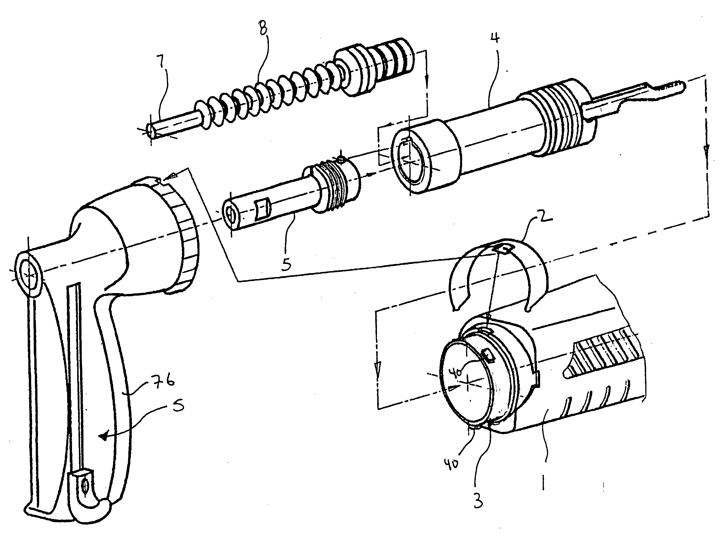
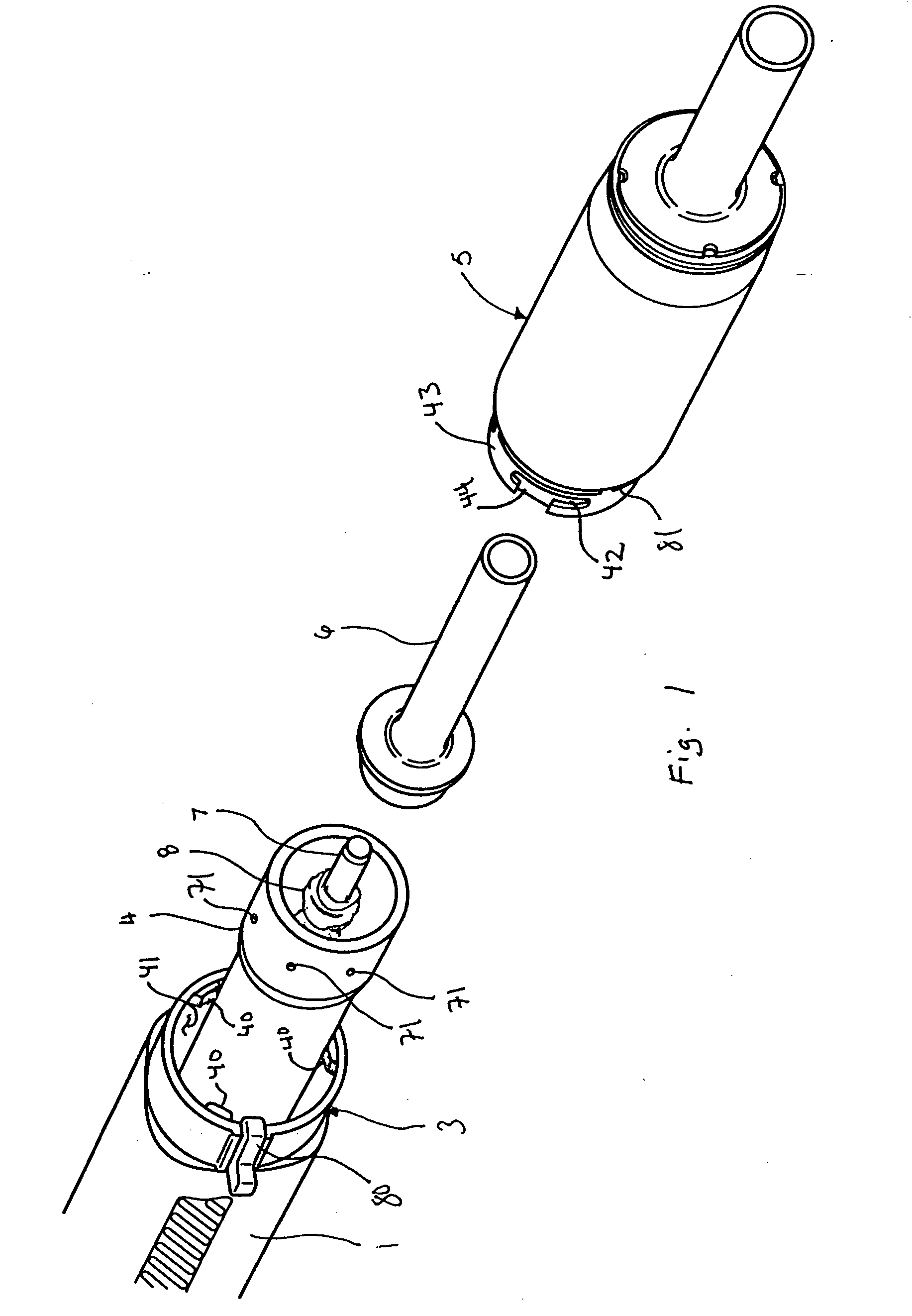
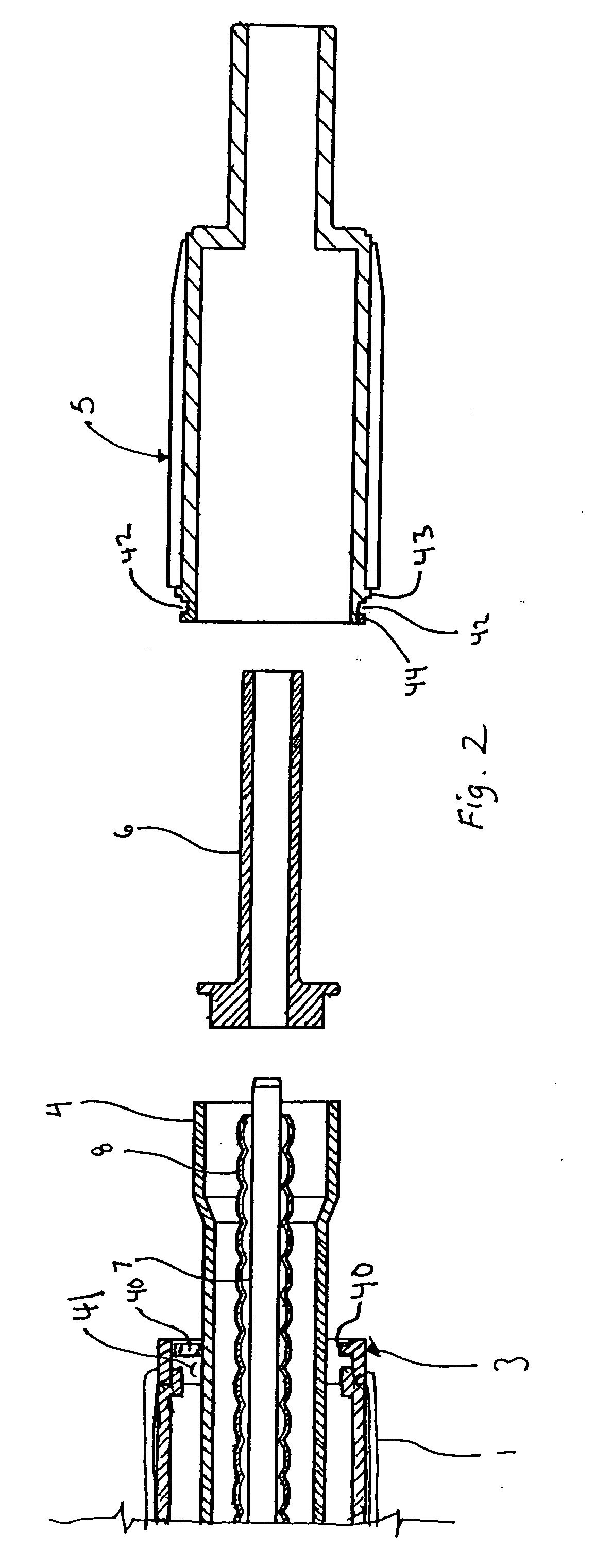
[0018]As shown in FIG. 10, the tool 100 has a handle housing 1, with a connecting ring 2. A two-part cylindrical receiver 3 is inserted into the housing 1 and is fixed within the housing 1. The receiver also receives a regulator bolt 20 and a regulator nut 21. A regulator shock absorber assembly 12 is attached to the receiver 3 where the receiver 3 interfaces with a cylindrical barrel 4. The barrel 4 is provided with an advance lever 10 that is restrained by an advance lever spring 11. The cylindrical piston 7 is inserted into the barrel 4. A rubber returner 8 fits over the length of the piston 7 and is surmounted by a cylindrical nose piece 6, which slides over the piston 7. A baseplate 5 fits over and restrains the nose piece 6, returner 8, piston 7 and barrel 4. The interiorily-threaded baseplate 5 is screwed onto the connecting ring 2. A firing pin assembly is inserted into the housing 1 behind the receiver 3. The firing pin assembly includes a cylindrical firing pin mechanism 1...


PUM


Abstract

A tool is provided with a barrel having a piston for driving a fastener into a substrate, the barrel being mounted for axial movement within a body of the tool and a nose piece being mounted forwardly of the barrel and being at least partially encapsulated by a base plate that connects to the receiver of the tool which encloses the barrel and piston, the present invention permiting ease of assembly and disassembly of the muzzle of the tool—the nose piece and base plate—by making the connection between the base plate and the receiver with a retainer element.

Description

BACKGROUND OF THE INVENTION[0001]The present invention relates to a power actuated fastening tool for driving a fastener, such as a nail, into a substrate, such as a concrete or steel structure.[0002]Power actuated tools for driving a fastener into a substrate conventionally comprise a barrel from which the fastener is expelled by means of a piston driven by detonation of an explosive charge. The barrel is mounted for axial movement within a receiver assembly which is in turn in the housingor body of the tool. A nose piece is placed forwardly of the barrel and received partially therein and is exposed outside of the housing. A base plate encapsulates most of the nose piece and the forward end of the barrel and attaches to the receiver.[0003]It is necessary to periodically disassemble the tool, particular the muzzle and barrel components for cleaning purposes and replacement of the returner which is generally made of rubber and wears out through repeated use, which requires removal o...

Claims


Application Information

Patent Timeline
IPC IPC(8): B25C1/18
CPCB25C1/14
Inventor EADES, CHADPRATT, CRAIG T.
Owner EADES CHAD
Why Eureka
Try Eureka