Network formation method and communication apparatus

a network and communication device technology, applied in the field of network formation methods, can solve the problems of inability to communicate between the two communication devices, inability to solve the above-described duplicate network construction problem, and inability to perform association processing between communicating communication devices

Active Publication Date: 2008-10-16
CANON KK
View PDF0 Cites 17 Cited by
  • Summary
  • Abstract
  • Description
  • Claims
  • Application Information

AI Technical Summary

Benefits of technology

[0017]An embodiment of the present invention is directed to a communication apparatus that prevents duplicate networks from being constructed when the communication apparatus forms a network.
[0018]Furthermore, an embodiment of the present invention is directed to a communication apparatus that enhances user convenience.

Problems solved by technology

In such a case, communication between the two communication devices is rendered impossible despite the fact that a common SSID has been set.
However, it is not disclosed how the above-described duplicate network construction problem can be resolved.
Moreover, even if it turns out to be possible to avoid such a duplicate network construction problem and a network having a unique SSID and BSSID is constructed, the following problems may still arise.
On the other hand, association processing is not performed between communicating communication devices in the ad-hoc mode.
In other words, user operability will suffer.
Furthermore, similar problems arise with other methods of use (for instance, when a digital camera is remotely operated by another digital camera).

Method used


Image

  • Network formation method and communication apparatus
  • Network formation method and communication apparatus
  • Network formation method and communication apparatus

Examples


embodiment 1

[0046]The first embodiment illustrates a case, in which processing used for ad-hoc network formation changes depending on whether the operations are performed on the image sender or image recipient side.

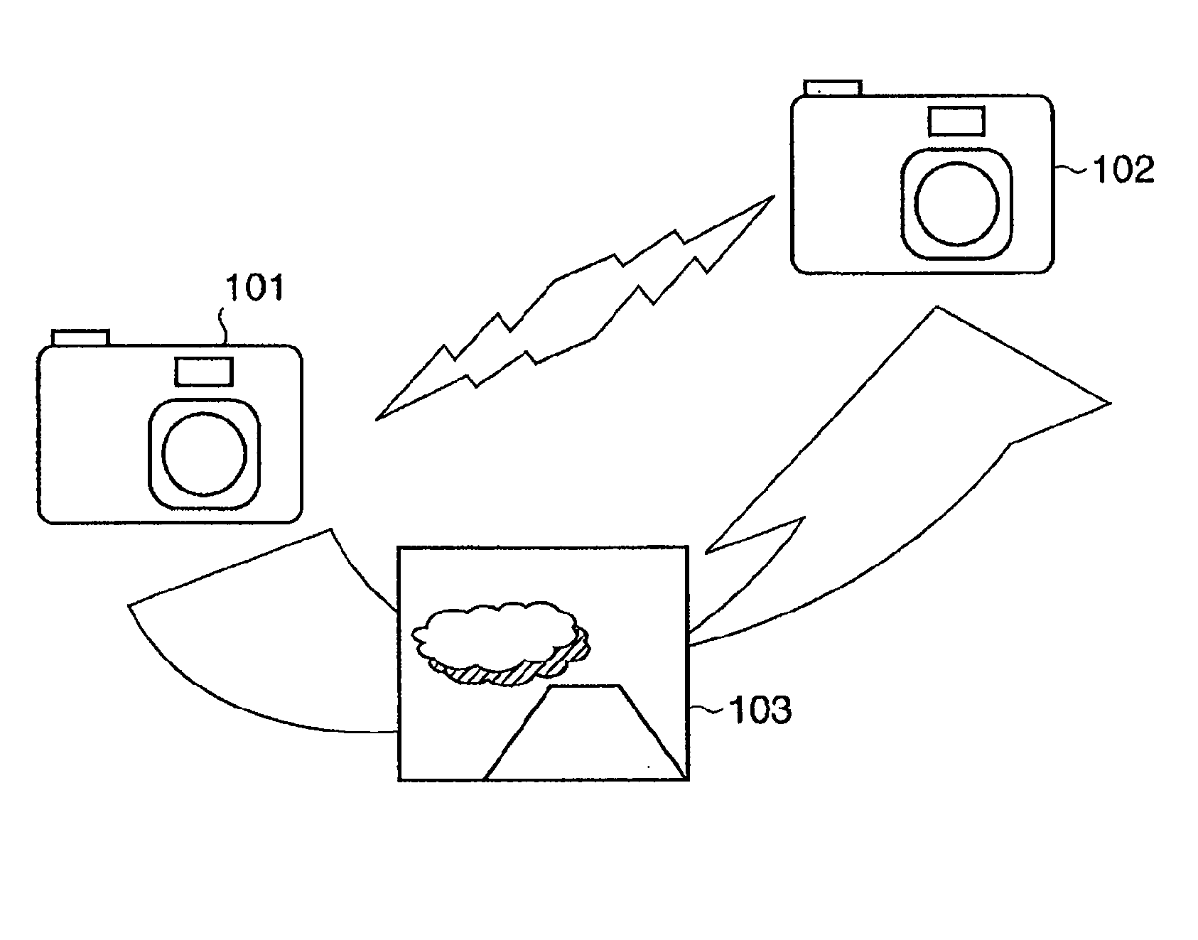
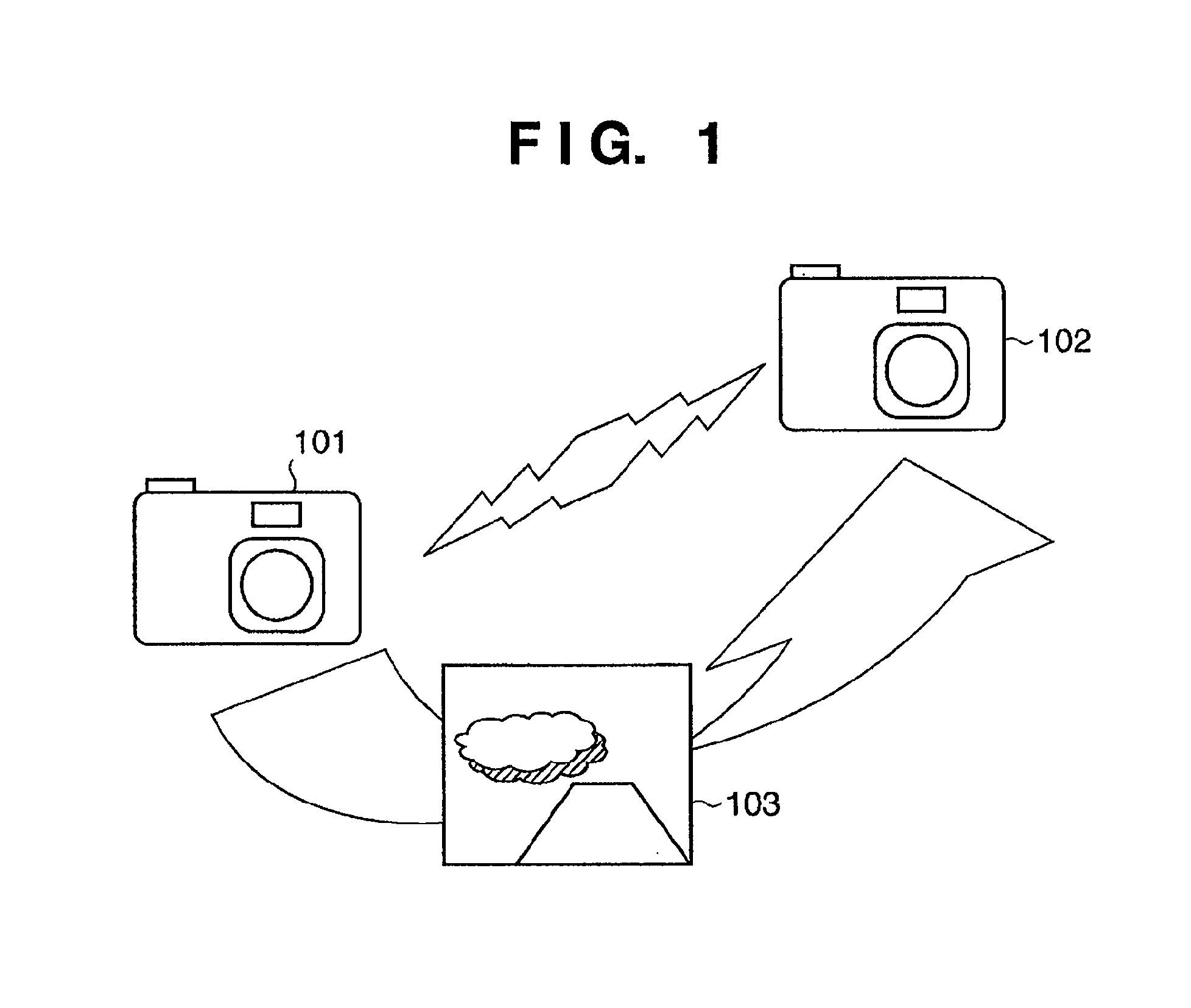
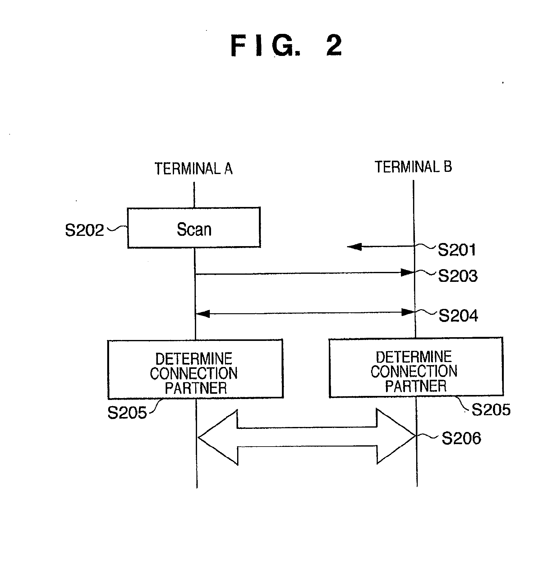
[0047]FIG. 2 is a diagram illustrating an operational sequence executed between two communication devices. In FIG. 2, the communication device A (digital camera 101) is a sender and the communication device B (digital camera 102) is a recipient.

[0048]First of all, the communication device B determines a BSSID based on the MAC address and transmits a beacon comprising the BSSID and a preset SSID (S201). On the other hand, the communication device A scans (searches for) networks with the preset SSID (S202). Scanning methods include passive scanning, during which the network is searched by monitoring a beacon, and active scanning, during which the network is searched by transmitting a probe request and receiving a response thereto. Although the case described herein makes use of passive...

embodiment 2

[0059]Next, a second embodiment of the present invention will be explained in detail by referring to drawings. In the second embodiment, FIGS. 3 and 6 to 8 are used to explain processing that takes place in a communication mode called the remote operation mode, in which a distant camera is remotely operated by a digital camera.

[0060]FIG. 8 is a schematic diagram illustrating remote operation in the second embodiment. FIG. 8 illustrates a case, in which a digital camera 802, which is a remotely operated camera, is remotely operated by a remote operating digital camera 801. In other words, the remote operating digital camera 801 is a device sending operational command data. Furthermore, the remotely operated digital camera 802 is a device receiving operational command data.

[0061]FIG. 6 is a flow chart illustrating processing on the remote operating communication device A (digital camera 801) side in the second embodiment. Moreover, FIG. 7 is a flow chart illustrating processing on the...

embodiment 3

[0069]Next, a third embodiment of the present invention will be explained in detail by referring to drawings. In the third embodiment, FIGS. 3, 9, and 10 are used to explain processing taking place in the communication partner registration mode. It should be noted that registration information transmitted and received in the communication partner registration mode includes MAC addresses, device types (digital camera, printer, etc.), device attributes (input device, output device, etc.), and corresponding application information (direct print feature, etc.).

[0070]FIG. 9 is a flow chart illustrating processing performed by the registration information-sending communication device A (digital camera 101) in the third embodiment. In addition, FIG. 10 is a flow chart illustrating processing taking place in a registration information-receiving communication device B (digital camera 102) side in the third embodiment. It should be noted that pre-determined SSIDs (hereafter referred to as reg...


PUM


Abstract

A determination is made as to whether a communication apparatus is a data sender or a data recipient and, based on the results of the determination, it is determined whether the apparatus constructs a network or joins a constructed network.

Description

BACKGROUND OF THE INVENTION[0001]1. Field of the Invention[0002]The present invention relates to a network formation method used for direct communication between communication apparatuses and a communication apparatus.[0003]2. Description of the Related Art[0004]Wireless LANs defined in IEEE802.11 (hereafter referred to as 802.11 wireless LANs) use the “infrastructure mode”, in which communication is effected via access points between communication devices (communication terminals), and the “ad-hoc mode”, in which communication is effected directly between communication devices. In the ad-hoc mode of an 802.11 wireless LAN, a communication device attempting to construct a network builds the network by transmitting a pilot signal called a beacon. Communication devices participating in the network join the network and effect communication based on information contained in such a beacon (beacon period, transmission rate, etc.).[0005]Moreover, wireless communication parameters, such as ...

Claims


Application Information

Patent Timeline
Patent Type & Authority Applications(United States)
IPC IPC(8): H04L12/28H04W8/00
CPCH04W8/005
Inventor NAGO, HIDETADA
Owner CANON KK
Why Eureka
Try Eureka