Artificial roof room-and-pillar shrinkage subsequent filling mining method

A filling mining method and room-and-pillar technology, applied in the direction of filling, ground mining, mining equipment, etc., can solve the problems of high mining cost, large stope exposure area, large ore loss rate, etc., to avoid personnel dispersion and blasting High efficiency and the effect of improving the recovery rate

Active Publication Date: 2018-10-16
MCC NORTH (DALIAN) ENG TECH CO LTD
View PDF4 Cites 17 Cited by
  • Summary
  • Abstract
  • Description
  • Claims
  • Application Information

AI Technical Summary

Problems solved by technology

Its main disadvantages are: the loss and dilution rate is high, generally 15% to 40%, when the ore is drawn under the overburden rock; the ventilation condition is poor, and a special ventilation tunnel needs to be constructed; the maintenance workload of the equipment is large, and the maintenance cost is high
Its main disadvantages are: due to segmental mining, the workload of development and mining is large, and the mining cost is high
The main disadvantages are: the exposed area of ​​the stope is large, the personnel and equipment work in the open field, the safety is poor, and the production capacity of the stope is small;
The main disadvantage is that the mining section is small, the mining process is complicated, and the production capacity of the stope is small;
[0007] The main advantage of the ordinary ore retention method is that the mining process is simple, and the main disadvantage is that the production capacity of the stope is small, a large number of columns and top and bottom columns need to be left, and the ore loss rate is relatively large;
[0008] Therefore, the caving method has a high loss and dilution rate and serious damage to the surface environment; the upward horizontal layered filling mining method has poor production safety and small stope production capacity; the approach method has complex mining processes and small stope production capacity; High ore loss rate and small stope production capacity

Method used


Image

  • Artificial roof room-and-pillar shrinkage subsequent filling mining method
  • Artificial roof room-and-pillar shrinkage subsequent filling mining method
  • Artificial roof room-and-pillar shrinkage subsequent filling mining method

Examples


Embodiment Construction

[0035] In the following description, for purposes of explanation, numerous specific details are set forth in order to provide a thorough understanding of one or more embodiments. It may be evident, however, that these embodiments may be practiced without these specific details. In other instances, well-known structures and devices are shown in block diagram form in order to facilitate describing one or more embodiments.

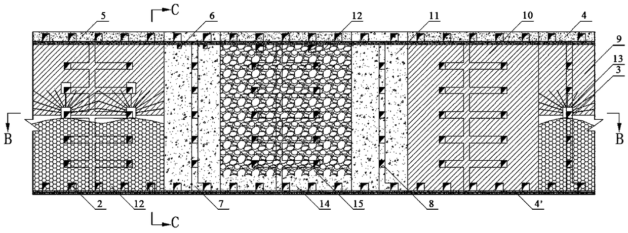
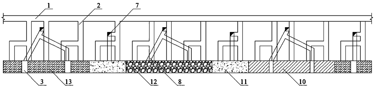
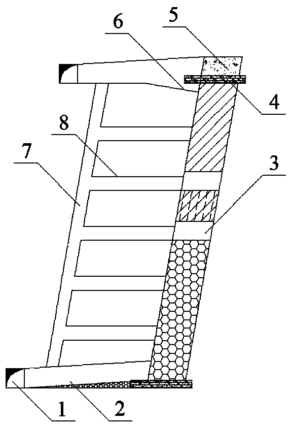
[0036] When mining the ore body, the ore body is divided into multiple stages in the vertical direction. Within the stage, the ore body is divided into ore rooms and pillars arranged at intervals along the direction of the ore body. Multiple mine houses and ore pillars form a panel . When mining, a panel is used as a mining unit, and the mine room and pillar are divided into multiple segments within the stage. In the following description, the mining of a panel will be used to illustrate the false roof column type mine retention and subsequent filling minin...


PUM

PropertyMeasurementUnit
heightaaaaaaaaaa
thicknessaaaaaaaaaa

Abstract

The invention provides an artificial roof room-and-pillar shrinkage subsequent filling mining method. The method comprises the steps that mine block structures are divided, specifically, an ore body is divided into multiple stages, ore chambers and ore pillars are divided in the stages in an ore body trend, and the ore chambers and the ore pillars are divided into multiple subsections; mining preparation and out seam mining preparation are conducted, specifically, a stage transportation haulage, a stage ore removal crosscut, a service ventilating raise, a subsection connection roadway, a filling inclined roadway and a drilling chamber are arranged; cutting is conducted; exploding is conducted, specifically, sector-shaped blast holes are drilled in the stage drilling chamber to cave down ores; stopping and ore removal are conducted, specifically, exploding is conducted from bottom to top in each stage, after each time of exploding, part of ores are transported from the stage ore removalcrosscut, remaining ores are shoveled out collectively on the stage ore removal crosscut after the ores are circulated to the topmost subsection ores are exploded and caved down, if the way of working to the dip is adopted during the stages, before upper stage stoping, an artificial roof is constructed on the top of the upper stage, and an artificial bottom is constructed on the bottom of the upper stage, and the artificial bottom of the upper stage is the stoping artificial roof of the next stage; and if the way of working from bottom up is adopted, the artificial roof of the next stage serves as the stoping artificial bottom of the upper stage.

Description

technical field [0001] The invention relates to the technical field of ore retention mining and filling mining technology, and more specifically, to a false-roof pillar-type ore retention followed by filling mining method. Background technique [0002] At present, the mining methods for medium-thick and sharply inclined broken ore bodies mainly include segmental caving method without pillar, segmental caving method with pillar, natural caving method, upward horizontal layered filling mining method, and upward approach filling method. , downward approach filling method, segmented empty field method, ordinary ore retention method, etc., among which: [0003] The main advantages of pillarless segmented caving method and natural caving method are: the mining method has simple structure, great flexibility, and does not require ore pillars; Mechanized supporting operation, good safety, low mining cost and high production efficiency. Its main disadvantages are: drawing ore under ...

Claims


Application Information

Patent Timeline
Patent Type & Authority Applications(China)
IPC IPC(8): E21C41/22E21F15/00
CPCE21C41/22E21F15/00
Inventor 郭子源蒋胜文周育王鹏
Owner MCC NORTH (DALIAN) ENG TECH CO LTD
Why Eureka
Try Eureka