Image processing method and related partial psf estimation method thereof

Inactive Publication Date: 2008-10-16
PRIMAX ELECTRONICS LTD
View PDF5 Cites 17 Cited by
  • Summary
  • Abstract
  • Description
  • Claims
  • Application Information

AI Technical Summary

Benefits of technology

[0007]Therefore, one objective of the present invention is to provide an image processing method to process a blurred image for generating a clear image without moving a lens and without limiting a lens type.
[0011]According to the method mentioned above, a clear image can be obtained without moving a lens and without limiting lens types, thus lowering the cost of the product and expanding the application scope. Also, image recovery can be performed corresponding to the difference of each part of the image, such that the quality of the recovery image can be improved.

Problems solved by technology

However, such mechanism requires manual control (for example, on a microscope) and is inconvenient.
In addition, since modern electronic devices tend to be compact and light, such mechanisms are not suitable for modern electronic devices.
However, such a method needs a specific lens, and a specific circuit to transform the outside image to form a specific blurred image, therefore it is not suitable for a normal apparatus.

Method used


Image

  • Image processing method and related partial psf estimation method thereof
  • Image processing method and related partial psf estimation method thereof
  • Image processing method and related partial psf estimation method thereof

Examples


Embodiment Construction

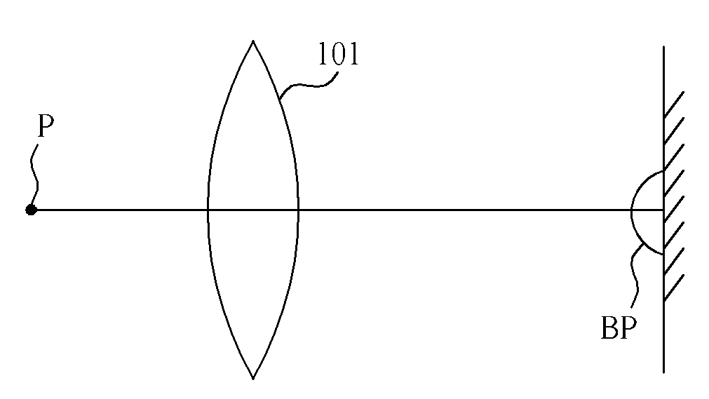
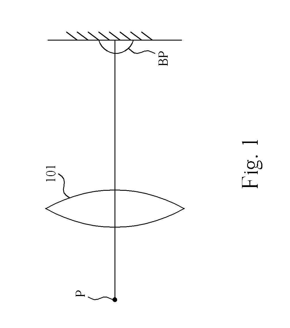
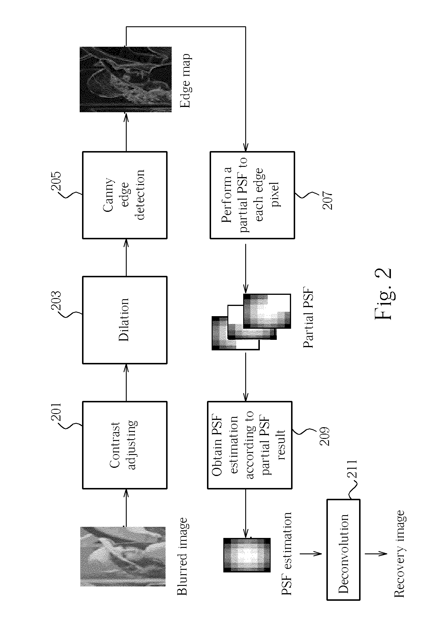
[0019]FIG. 2 is an image processing method according to a first preferred embodiment of the present invention. As shown in FIG. 2, an edge map is obtained after a blurred image is processed by an adjusting process 201, a dilation process 203 and a Canny edge detection process 205. Then, in step 207, partial Point Spread Function (PSF) is performed to each edge pixel of the edge map to obtain a plurality of partial PSF estimation results. Next, in the step 209, PSF estimation result of the whole image can be obtained according to a plurality of partial PSF estimation results. In this embodiment, all partial PSF estimation results are averaged to obtain a PSF estimation result, but it is not meant to limit the scope of the present invention. Then, the step 211 is performed according to the PSF estimation result, such that deconvolution is applied to an image to obtain a recovery image. However, the PSF estimation result from the step 209 can be utilized for other usages and is not lim...


PUM


Abstract

An image processing method includes (a) performing edge detection to an image to obtain a plurality of the edge pixels of the image; (b) performing partial PSF estimation to each of the edge pixels to generate a plurality of partial PSF estimation results; and (c) generating a PSF estimation result according to the partial PSF estimation results.

Description

BACKGROUND OF THE INVENTION[0001]1. Field of the Invention[0002]The present invention relates to an image processing method, and particularly relates to an image processing method utilizing a partial PSF estimation method and the utilized partial PSF estimation method.[0003]2. Description of the Prior Art[0004]FIG. 1 is a schematic diagram illustrating how a blurred image is formed. As shown in FIG. 1, a pixel P will be transformed to a blurred image region BP after passing a lens 101. Therefore a focus of an apparatus utilizing the lens 101, such as an optical microscope or a camera should be adjusted such that the pixel P can be transformed to a clear pixel. Normally, a mechanical adjusting mechanism is utilized to adjust the focus, that is, adjusting the mechanical structure of the apparatus to obtain suitable focus. However, such mechanism requires manual control (for example, on a microscope) and is inconvenient. In addition, since modern electronic devices tend to be compact a...

Claims


Application Information

Patent Timeline
IPC IPC(8): G06K9/40
CPCH04N5/217G06T5/003G06T5/20G06T7/0085G06T2207/20036G06T7/13H04N23/81G06T5/73
Inventor CHOU, CHAO-CHINHSU, CHIA-CHUNKUO, CHUNG-CHIEHCHOU, WEN-LUNGHSI, CHEN-NING
Owner PRIMAX ELECTRONICS LTD
Why Eureka
Try Eureka