Camera Integral With Optical Fiber

a technology of optical fibers and integrals, applied in the field of integrals of cameras with optical fibers, can solve the problems of not being able to form parts using fittings, and achieve the effects of preventing a decrease in light amount, reducing the amount of light, and being easy to produ

Inactive Publication Date: 2008-10-16
PANASONIC CORP
View PDF5 Cites 5 Cited by
  • Summary
  • Abstract
  • Description
  • Claims
  • Application Information

AI Technical Summary

Benefits of technology

[0008]A purpose of the invention made in the above-mentioned background is to provide a camera integral with optical fibers that has sufficient waterproof capability, is easy to produce, and prevents a decrease in the amount of light.Means for Solving the Problems

Problems solved by technology

For this reason, it is not easy to form the part using the fitting, to incorporate the part, and to incorporate the optical fiber component into the housing.

Method used


Image

  • Camera Integral With Optical Fiber
  • Camera Integral With Optical Fiber
  • Camera Integral With Optical Fiber

Examples


Embodiment Construction

[0040]Now, the invention will be described in detail. However, the following detailed description and appended drawings are not intended to limit the invention. Alternatively, the scope of the invention is defined by the appended claims.

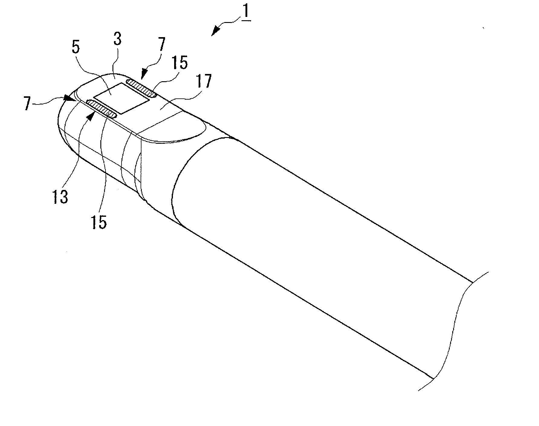
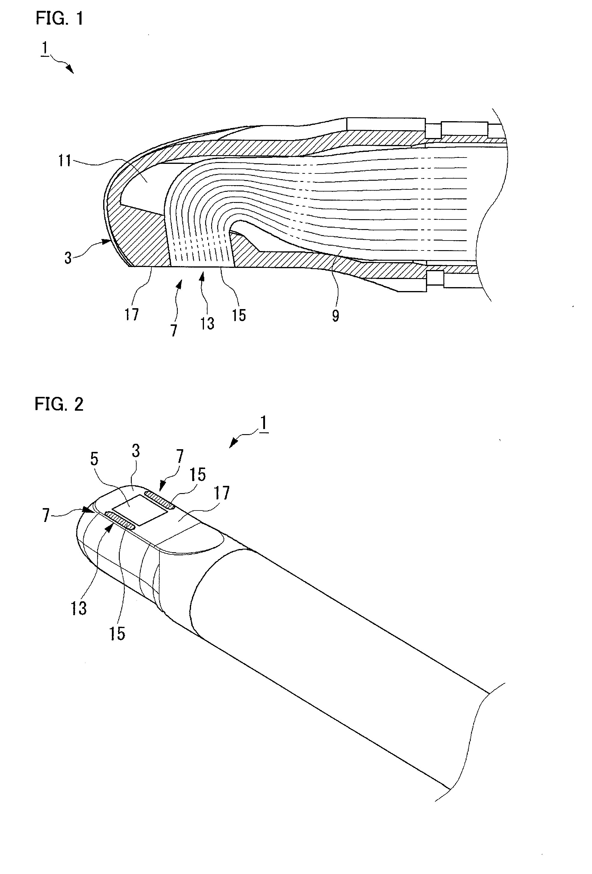
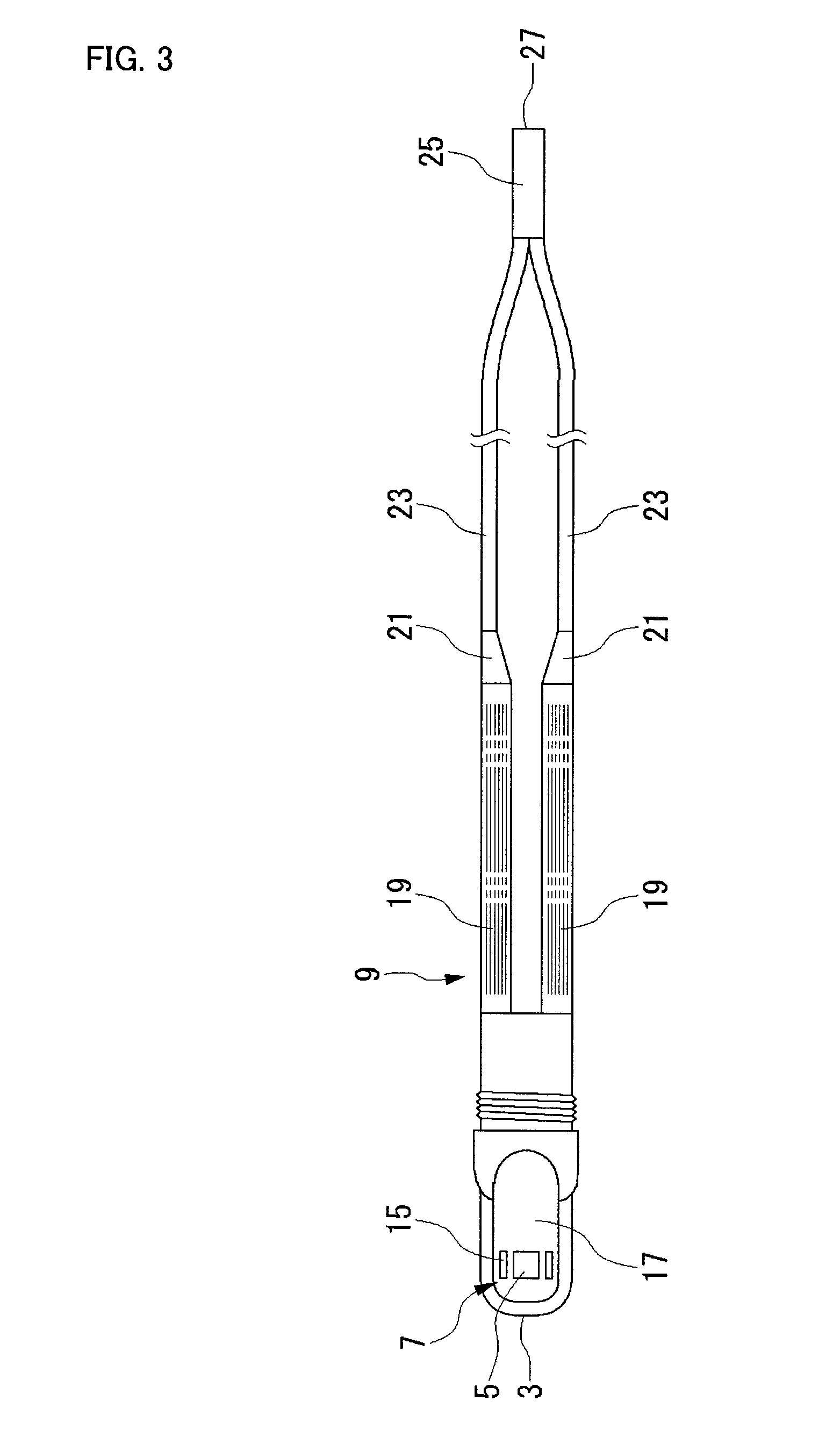
[0041]A camera integral with optical fibers of this embodiment comprises: a tubular housing having an emission window; and a unitized optical fiber bundle which is a bundle of light guiding optical fibers unitized on an inner surface of the housing, wherein the unitized optical fiber bundle is provided on and bonded to the inner surface of the housing with the fibers bonded together by a bonding agent, and wherein an end section of the unitized optical fiber bundle reaches the emission window to be exposed.

[0042]In this configuration, since the above unitized optical fiber bundle, a bundle of optical fibers unitized on the inner surface of the housing, is provided, optical fibers as a separate component bundled with a front-end fitting can be elimina...


PUM


Abstract

A camera (1) has a tubular housing (3) having an emission window (7). A unitized optical fiber bundle (9) is provided on the inner surface of the housing (3) by utilizing a bundle of light guiding optical fibers on the inner surface. The unitized optical fiber bundle (9) is placed on and bonded to the inner surface of the housing (3) with the fibers bonded together by a bonding agent. An end section of the unitized optical fiber bundle (9) reaches the emission window (7) of the housing (3) to be exposed. The camera (1) has sufficient waterproof capability and is easy to produce, and capable of avoiding a decrease in the amount of light.

Description

TECHNICAL FIELD[0001]The present invention relates to a camera integral with optical fibers.BACKGROUND ART[0002]Conventionally, a camera integral with optical fibers is used, for example, for dental or other medical uses. This kind of camera is required to be small, as well as to light up an area to be treated. In order to meet these requirements, a camera is provided with an illumination device using optical fibers. Such a camera is disclosed, for example, in Japanese laid-open publication No. Hei. 8-332170A (pages 3 to 4, and FIG. 1).[0003]FIG. 11 shows a front-end part of a conventional camera integral with optical fibers. A camera 101 has a tubular housing 103, in which a CCD or other imaging devices and an image processing circuit are housed. On the side of the front end of the housing 103 is provided a shooting window 105, in which a prism is inserted. Light that enters through the shooting window 105 is bent by the prism and guided in the tube direction. Emission windows 107 ...

Claims


Application Information

Patent Timeline
Patent Type & Authority Applications(United States)
IPC IPC(8): G02B6/06A61B1/00G02B23/24G02B23/26H04N5/225
CPCA61B1/07A61B1/24G02B23/2469G02B23/2484H04N5/2251H04N5/2252H04N2005/2255A61B1/00177A61B1/0615H04N23/555H04N23/50H04N23/51
Inventor UCHIDA, TAMOTSUKATO, HIDETO
Owner PANASONIC CORP
Why Eureka
Try Eureka