

Novel needle driver for magnetic resonance elastography
a magnetic resonance elastography and needle driver technology, applied in the field of applicative for sensitive and specific detection of small tumors, can solve the problems of failing to teach or suggest combining biopsy or acupuncture needle with any type of driver, and achieve the effect of accurate determination of brain stiffness, reducing unnecessary biopsies and interventions, and increasing sensitivity and specificity of mre imaging
- Summary
- Abstract
- Description
- Claims
- Application Information
AI Technical Summary
Benefits of technology
Problems solved by technology
Method used
Image

Examples
Embodiment Construction
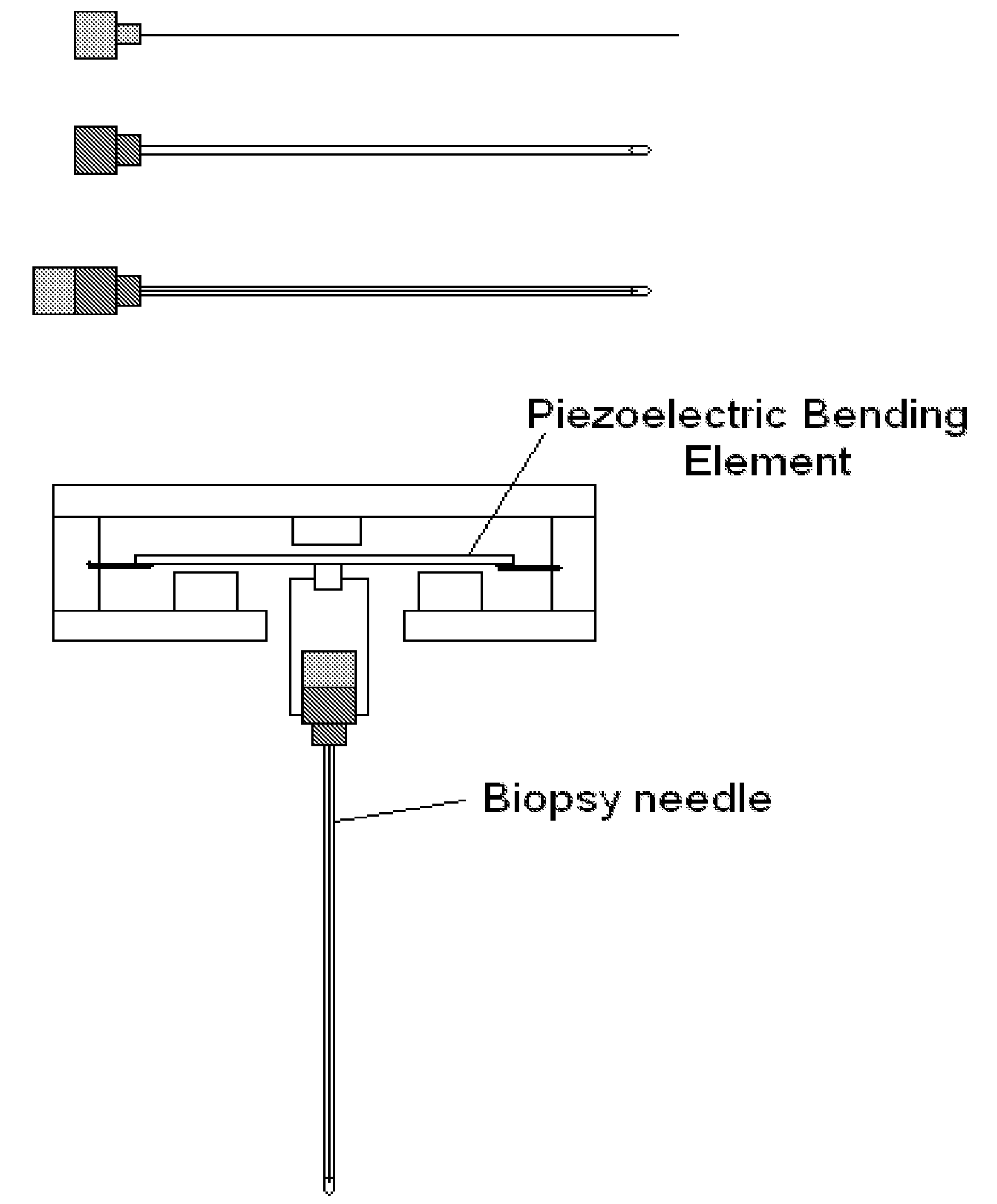
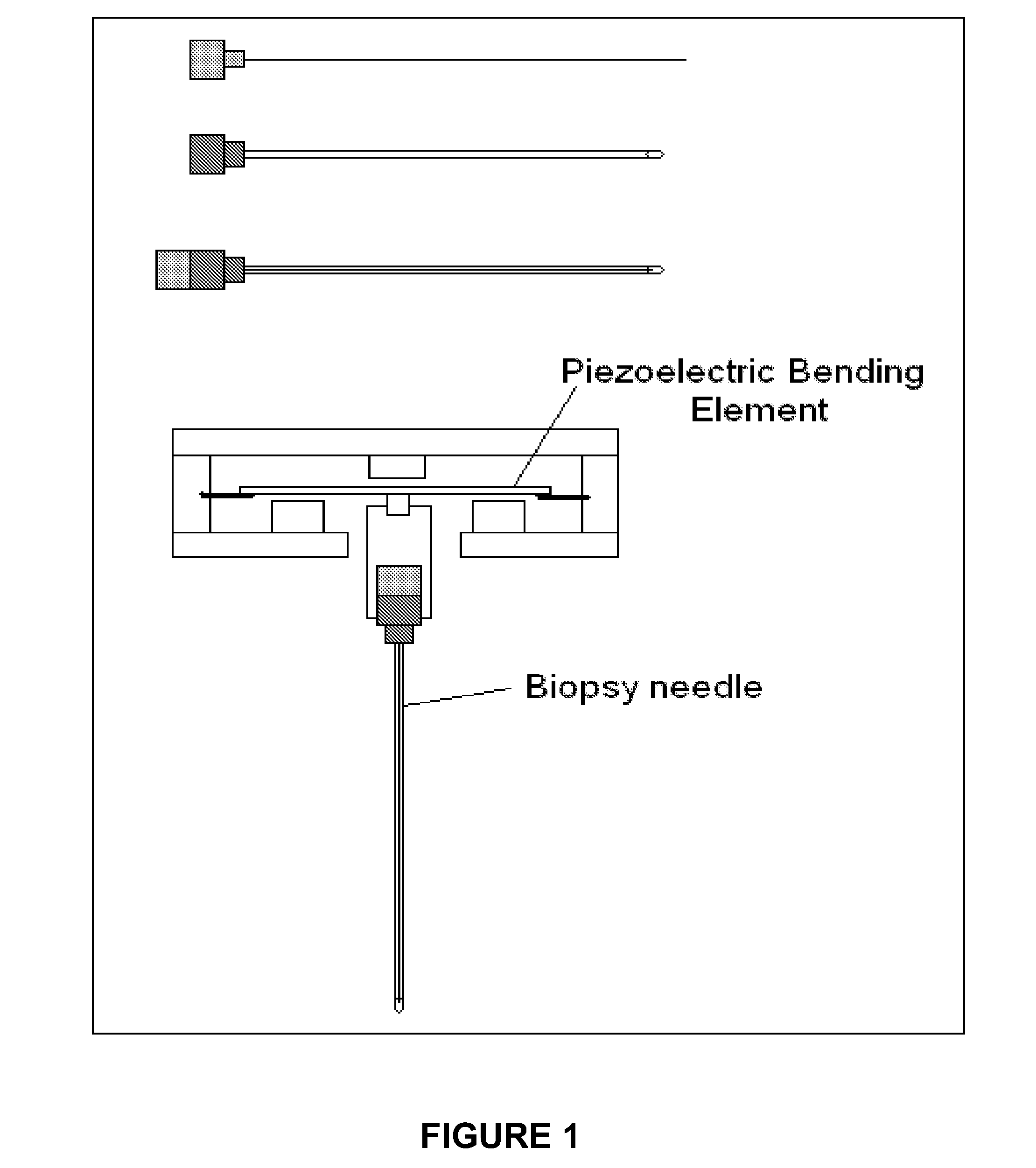
[0065]FIGS. 1 and 9 reference a cross-sectional view of a mechanically driven needle biopsy device and associated needle system.
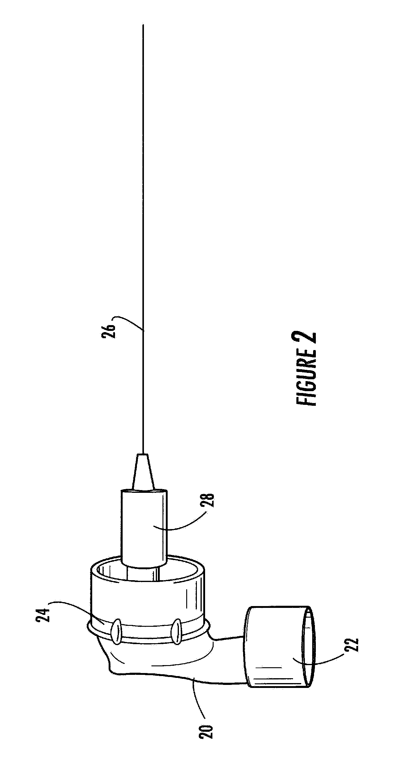
[0066]FIG. 2, is a perspective view of a drum needle driver embodiment, in accordance with the present invention, which can be used as a mechanical stimulus in MRE for producing a plane wave, as opposed to a spherical wave as is produced by a surface driver. The drum driver is formed from any polymer which is safe to use within an MRI machine, e.g. polycarbonate, high density polyethylene, polypropylene, ethylene-propylene copolymer, nylon, and the like. The drum needle driver includes a housing 20, which has an inlet end 22 for influx of a pulsatile flow of gas, e.g. air, nitrogen or the like, or the energy output supplied by an alternative wave generation means, e.g. a speaker (not shown) which impacts upon diaphragm 24, and causes a rhythmic undulation of the diaphragm 24, and a concomitant movement of the biopsy needle 26, which is in removable mechanic...
PUM
 Abstract
Description
Claims
Application Information