
Implantable Heart Stimulation Device and Method

a heart stimulation and implantable technology, applied in heart stimulators, electrotherapy, therapy, etc., can solve the problems of pacemaker-mediated tachycardia (pmt) of heart stimulation devices

Inactive Publication Date: 2008-10-16
ST JUDE MEDICAL
View PDF13 Cites 2 Cited by
  • Summary
  • Abstract
  • Description
  • Claims
  • Application Information

AI Technical Summary

Benefits of technology

[0012]An object of the present invention is to provide a cardiac heart stimulation device with which it is possible to detect a certain loop of events that if the heart stimulation device were (or is) in operation in a patient could be (or can be) a pacemaker-mediated tachycardia of the above kind.
[0030]According to a further embodiment of the heart stimulation device, the change in operation involves preventing at least one pacing pulse of the second ventricle pacing circuit from being generated.
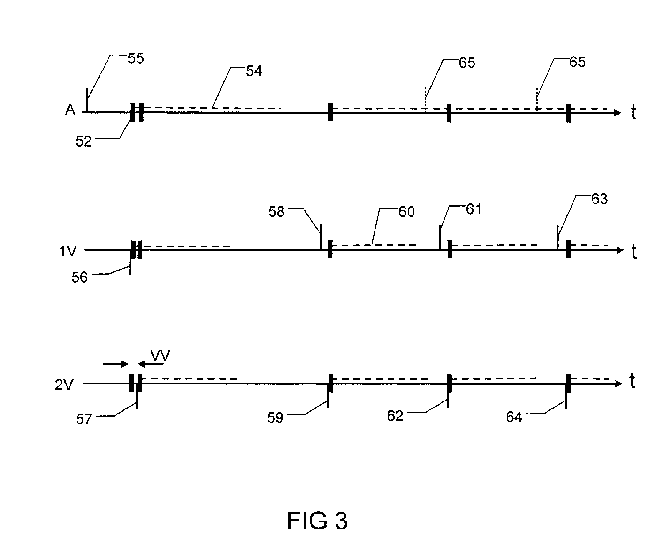
[0038]According to a further embodiment of the heart stimulation device, the change in operation involves temporarily shortening the pacing parameter which is the time between an event sensed by the first ventricle sensing circuit and the subsequent pacing pulse, during the same time cycle, delivered with the second ventricle pacing circuit, and thereafter return to the normal operation of the heart stimulation device. By shortening the mentioned pacing parameter, it is less likely that the electrical activity caused by a pacing pulse to the second ventricle will be transferred and sensed in the first ventricle. Consequently, it can be possible to break the operation pattern in this manner.
[0042]According to a further embodiment of the heart stimulation device, the control circuit is also configured to carry out an analysis of the stored sequence of heart stimulation device events, and based on this analysis, to automatically change the one or more pacing parameters, such that a future loop of events of the above defined kind is prevented if the heart stimulation device is in operation in a patient. According to this alternative, the device itself thus automatically carries out the necessary change in pacing parameters in order to prevent future occurrences of the endless loop of events.
[0044]a) changing at least one sensitivity setting of the operation of the heart stimulation device, such that the heart stimulation device is less sensitive, and thus less likely to sense at least one kind of event, the sensing of which could trigger the above defined loop of events if the heart stimulation device is in operation in a patient,
[0047]d) extending at least one blanking or refractory period of the operation of the heart stimulation device, such that the heart stimulation device is less likely to react on at least one kind of event, which, if the heart stimulation device reacted on it, could trigger the above defined loop of events if the heart stimulation device is in operation in a patient.

Problems solved by technology

A problem that occurs in connection with heart stimulation devices is pacemaker-mediated tachycardia (PMT).

Method used


Image

  • Implantable Heart Stimulation Device and Method
  • Implantable Heart Stimulation Device and Method
  • Implantable Heart Stimulation Device and Method

Examples


Embodiment Construction

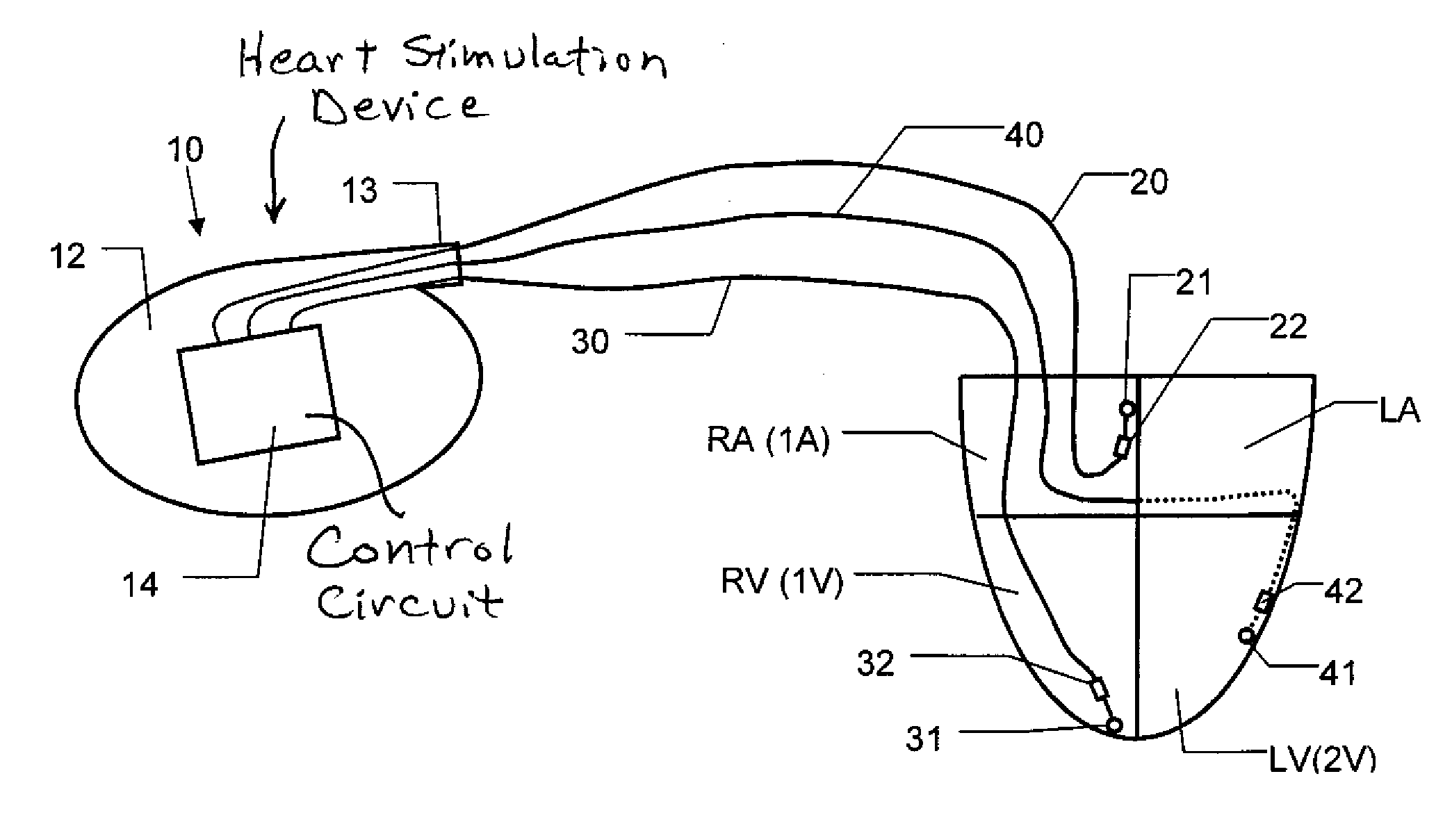
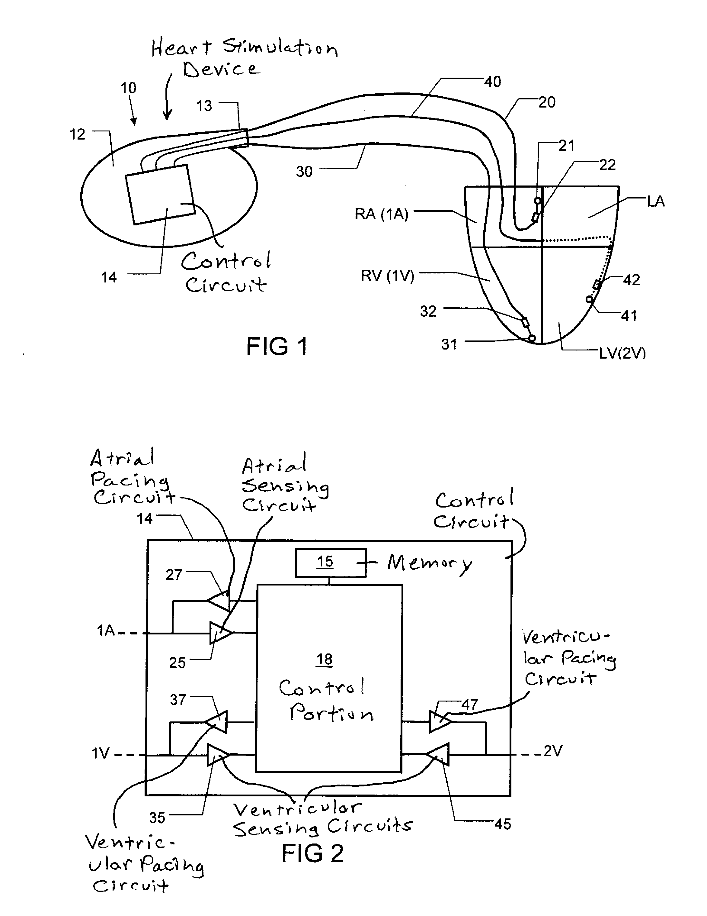
[0064]FIG. 1 shows schematically an embodiment of an implantable heart stimulation device 10 according to the invention. The device 10 has a housing 12. The housing 12 includes a control circuit 14. The device 10 has a connector portion 13. Via the connector portion 13, the device 10 can be connected to different leads. In FIG. 1 the device 10 is connected to three leads 20, 30 and 40.

[0065]The lead 20 includes a pacing and sensing electrode 21, 22. In the shown example, this electrode 21, 22 is a bipolar electrode with a tip portion 21 and a ring portion 22. However, it is within of the scope of the invention that instead unipolar electrodes can be used, as is known to those skilled in the art. Similarly to the lead 20, the lead 30 includes a pacing and sensing electrode 31, 32 and the lead 40 includes a pacing and sensing electrode 41, 42. The device 10 together with the leads 20, 30, 40 and the electrodes 21, 22; 31, 32; 4142 can be said to constitute an implantable heart stimula...


PUM


Abstract

The above object is achieved in accordance with the present invention by a cardiac stimulation device for stimulating a heart having a first ventricle and a second ventricle. The device includes a first ventricle sensing circuit that is configured to communicate with a first ventricle sensing electrode suited to be positioned in or at the first ventricle, to enable the first ventricle sensing circuit to sense the first ventricle. The device also includes a second ventricle pacing circuit, configured to communicate with a second ventricle pacing electrode suited to be positioned in or at the second ventricle of the heart, to enable the second ventricle pacing circuit to pace the second ventricle. The device includes a control circuit that operates with time cycles corresponding to normal heart cycles. The control circuit is configured to, within such a time cycle, to detect a cardiac event in the first ventricle with the first ventricle sensing circuit and, after a time duration that is greater than or equal to zero, to cause the second ventricle pacing circuit to deliver a pacing pulse. The control circuit is also configured to detect the aforementioned loop of events indicative of the pacemaker-mediated tachycardia by detecting one or both of (i) the regularity of one or more repetitious events related to operation of the first ventricle sensing circuit or the second ventricle pacing circuit, and (ii) a repetitive operation pattern of the heart stimulation device. The control circuit is configured to determine if the detected regularity satisfies a predetermined regularity criterion and to determine if the operation pattern satisfies a predetermined operation pattern criterion. Based on whether one or both of these criteria are satisfied, the control circuit determines whether the aforementioned loop of events, and thus the presence of pacemaker-mediated tachycardia, is likely to exist.

Description

BACKGROUND OF THE INVENTION[0001]1. Field of the Invention[0002]The present invention relates to an implantable heart stimulation device with which it is possible to stimulate both the ventricles of a heart, i.e. a bi-ventricular pacer. The heart stimulation device can be a so-called pacemaker or an ICD (implantable cardioverter defibrillator) which also includes a pacing function.[0003]The invention also relates to a method of, in a patient who is treated with a bi-ventricular cardiac heart stimulation device, detecting a pacemaker-mediated tachycardia of a certain kind.[0004]2. Description of the Prior Art[0005]Several different implantable devices for stimulating a heart are known. The devices are normally able to sense the electrical activity of the heart. Some implantable devices are able to deliver stimulation pulses to and / or sense the right atrium (in some cases even the left atrium) and also to deliver stimulation pulses to and sense both the left and right ventricles.[0006...

Claims


Application Information

Patent Timeline
IPC IPC(8): A61N1/368
CPCA61N1/3622
Inventor BJORLING, ANDERS
Owner ST JUDE MEDICAL
Learn More