Angular velocity sensor

Inactive Publication Date: 2008-10-23
TAMAGAWA SEIKI CO LTD
View PDF12 Cites 0 Cited by
  • Summary
  • Abstract
  • Description
  • Claims
  • Application Information

AI Technical Summary

Benefits of technology

[0009]The present invention has been made in view of the above-mentioned circumstances and provides an angular velocity sensor that has a simplified fabricating process for fixing a cover to a mounting portion made of resin, and consequently the fabricating cost thereof is reduced.

Problems solved by technology

An impact conveyed to the vibrator may cause the angular velocity sensor to malfunction.
The insulating portion increases the fabricating cost and the height of the angular velocity sensor.
The above insulation increases the fabricating cost.
Further, the mounting portion made of resin may be damaged by impact at the time of folding the engaging portion 60.
The above requirements complicate the fabricating process and increase the fabricating cost.
Thus, the process of fixing the cover to the mounting portion is complicated.

Method used


Image

  • Angular velocity sensor
  • Angular velocity sensor
  • Angular velocity sensor

Examples


Embodiment Construction

[0020]A description will now be given of embodiments of the present invention with reference to the accompanying drawings.

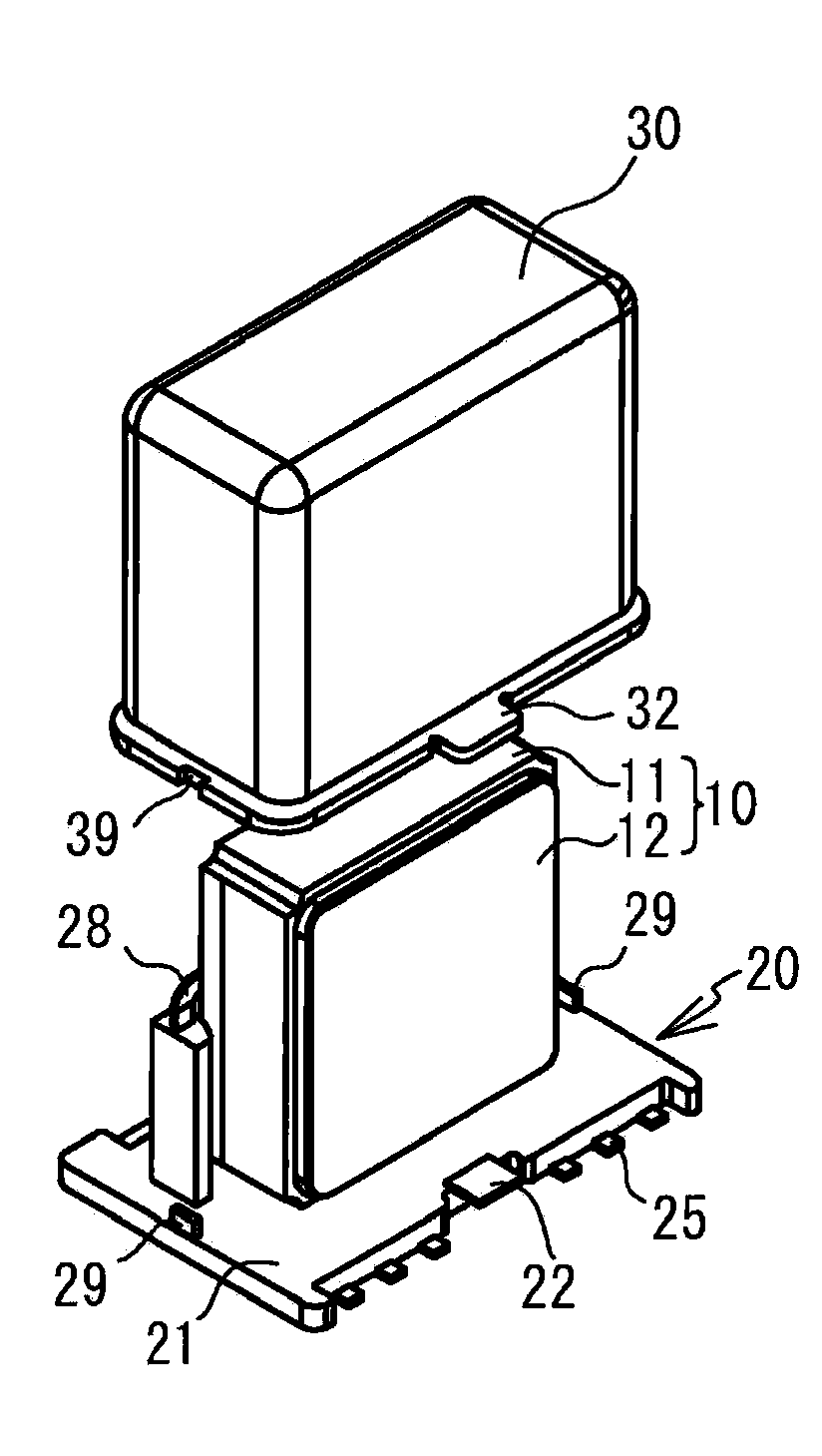
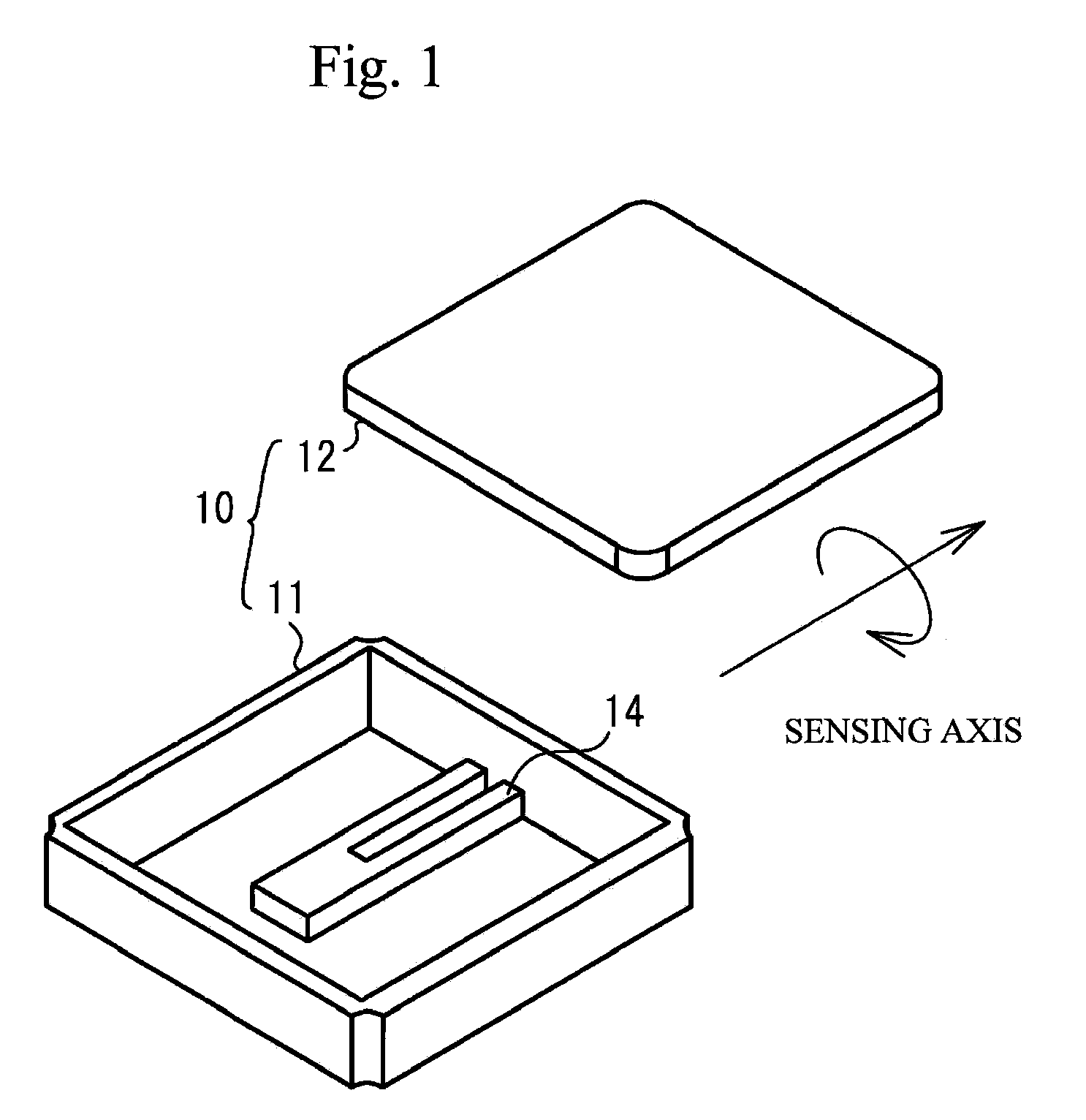
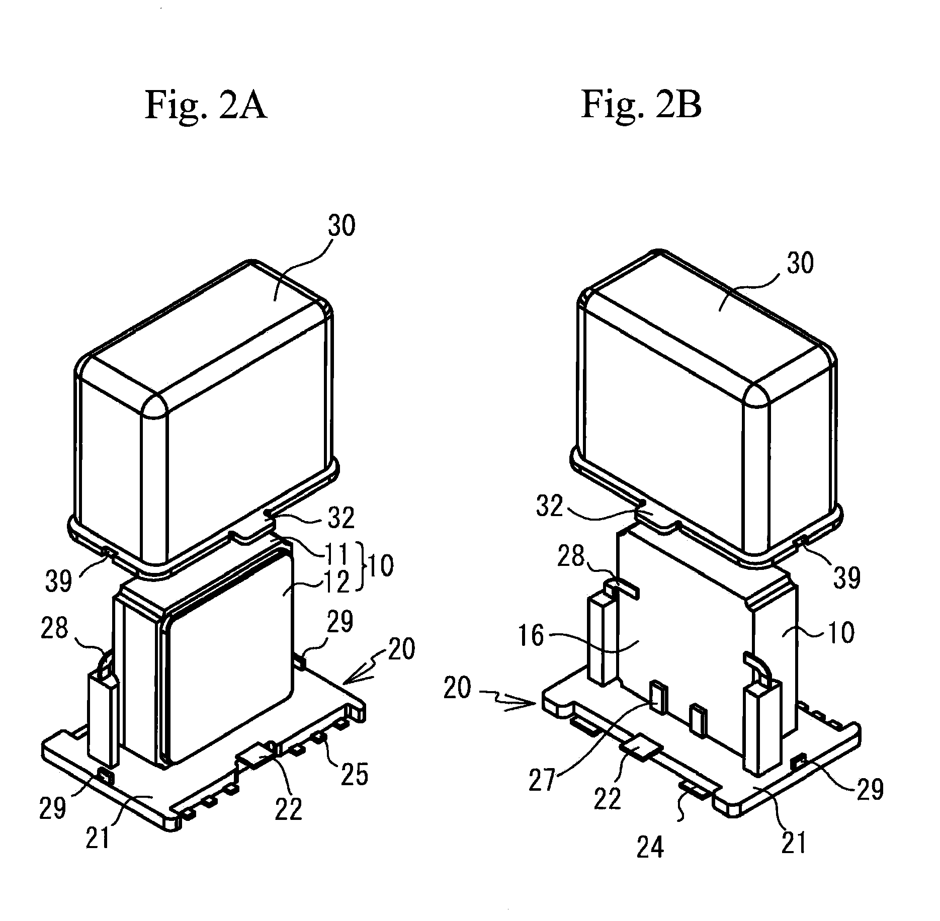
[0021]FIG. 1 is a perspective view of a package 10 of an angular velocity sensor in accordance with a first embodiment. Referring to FIG. 1, a tuning-fork vibrator 14 sensing an angular velocity is housed in a cavity of a main body 11 of the package 10 made of ceramic. The tuning-fork vibrator 14 is electrically connected to pad electrodes (not shown) on the backside of the main body 11, and is mounted on the main body 11 via a vibration-proofing portion (not shown) for restraining the tuning-fork vibrator 14 from being affected by unnecessary vibration applied to the package 10. The sensing axis of the angular velocity is in the arm direction of the tuning-fork vibrator 14, and it is possible to sense the angular velocity about the sensing axis. A cap portion 12 made of Kovar (nickel-cobalt ferrous alloy) is attached to the main body 11 so as to house the tuning...


PUM


Abstract

An angular velocity sensor includes: a package housing a vibrator to sense an angular velocity; a mounting portion mounting the package, the mounting portion having a first terminal for making a connection with the package; a second terminal for making an external connection, and a resin portion covering the first and second terminals so that a part of the first terminal and a part of the second terminal are exposed; and a cover having a joint portion made of a metal and covering the package, the cover being fixed to the mounting portion by joining the joint portion to a joint terminal made of a metal and provided to the mounting portion.

Description

BACKGROUND OF THE INVENTION[0001]1. Field of the Invention[0002]The present invention generally relates to an angular velocity sensor, and more particularly, to an angular velocity sensor in which a package for housing a vibrator is mounted on a mounting portion and is covered with a cover.[0003]2. Description of the Related Art[0004]An angular velocity sensor is a sensor that senses an angular velocity in rotation, and is used in systems for image stabilization of cameras, for automotive navigation, for stability control of vehicles or postures of robots, and the likes. FIG. 9 of Japanese Patent Application Publication No. 2003-28647 (hereinafter referred to as Document 1) discloses a technique in which a mounting portion (a base portion 55a) and a cover (a cover portion 55b) of a pin-mounting-type angular velocity sensor are made of a metal.[0005]The angular velocity sensor has a vibrator, and a vibrating mode thereof senses an angular velocity. An impact conveyed to the vibrator ...

Claims


Application Information

Patent Timeline
IPC IPC(8): G01P15/097G01C19/5628G01P1/02
CPCG01C19/56G01P3/00
Inventor OTA, KAZUHIROYACHI, MASANORI
Owner TAMAGAWA SEIKI CO LTD
Why Eureka
Try Eureka