Scroll compressor

Inactive Publication Date: 2010-08-19
LG ELECTRONICS INC
View PDF9 Cites 2 Cited by
  • Summary
  • Abstract
  • Description
  • Claims
  • Application Information

AI Technical Summary

Benefits of technology

[0011]The scroll compressor in accordance with the present invention is configured to have the discharge outlet of the fixed scroll and the discharge guide groove of the orbiting scroll formed in non-circular shapes such as a heart shape, thus it is capable of preventing the discharge pressure of the refrigerant from being incom

Problems solved by technology

But, when the two pressure ratios are not equal to each other, the loss increases.
For example, in case that the operating pressure ratio is set to be higher than the designed pressure ratio, a pressure of gas in the compression chambers does not implement the discharge pressure.
Thus, a pressure actually discharged is lower than a pressure needed for loads, which causes a compression incompletion.
On the other hand, in case that the operating pressure ratio is lower than the designed pressure ratio, even though the pressure needed for the load is low, the orbiting wrap does not yet reach the discharge initiation angle

Method used


Image

  • Scroll compressor
  • Scroll compressor
  • Scroll compressor

Examples


Embodiment Construction

[0017]Hereafter, description will now be given in detail of one embodiment of a scroll compressor according to the present invention with accompanying drawings.

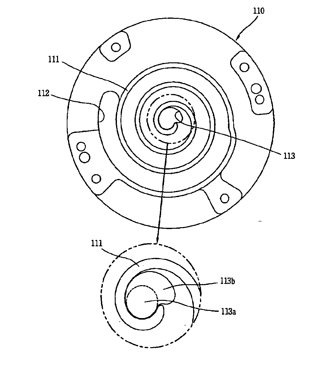
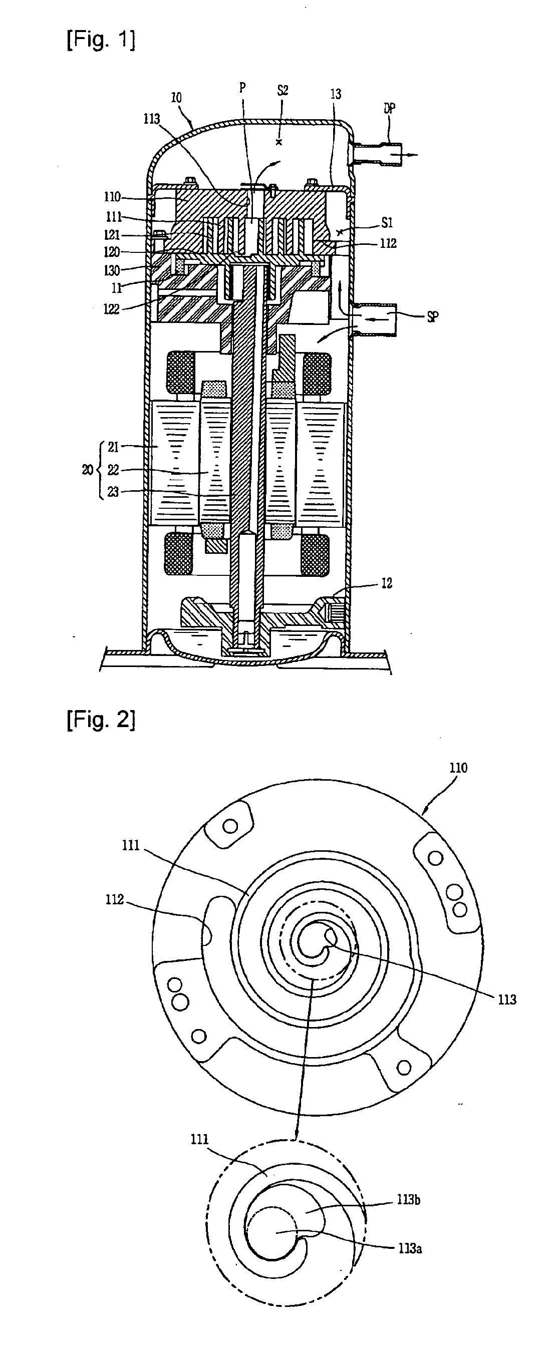
[0018]As shown in FIG. 1, the scroll compressor includes a casing 10, a driving motor 20 installed at an upper portion of the casing 10 and generating a rotational force and a compression unit 30 installed at an upper portion of the case 10 and compressing a refrigerant after receiving the rotational force generated from the driving motor 20.

[0019]The casing 10 has an inner space in a hermetic state. A suction pipe (SP) is communicated with a middle of a wall surface of the casing 10 so as to suck the refrigerant from a refrigeration cycle apparatus. And, a discharge pipe (DP) is communicated with an upper portion of the wall surface of the casing 10 so as to discharge the refrigerant having been compressed in the compression unit 30 to the refrigeration cycle apparatus. A main frame 11 and a sub frame 12 are respectively fix...


PUM


Abstract

The present invention relates to a scroll compressor. The scroll compressor is configured to have a discharge outlet (113) of a fixed scroll (110) and a discharge guide groove of an orbiting scroll (120) for med in non-circular shapes such as a heart shape. Accordingly, it is capable of preventing a refrigerant from being incompletely or excessively compressed without additional bypass valves, thereby being capable of reducing a fabrication cost of the compressor. And, since it is not required to consider interference by other components at the time of installation of a bypass valve, it is capable of simplifying a fabrication process.

Description

TECHNICAL FIELD[0001]The present invention relates to shapes of a discharge outlet and a discharge guide groove in a scroll compressor.BACKGROUND ART[0002]Generally, a compressor serves to convert mechanical energy into compressive energy of fluid. Compressors may be categorized into a reciprocating type, a rotary type, a vane type and a scroll type according to a compressing mechanism with respect to fluid.[0003]The scroll compressor is provided with a driving motor for generating a driving force and a compression unit for compressing a refrigerant, compressive fluid by receiving the driving force from the driving motor, within a hermetic casing.[0004]The compression unit consists of a fixed scroll fixed at the casing by being provided with a fixed wrap and an orbiting scroll performing an orbiting motion by being provided with an orbiting wrap to be engaged with the fixed wrap. The fixed wrap and the orbiting wrap have the same base circle radius and are formed to have one involut...

Claims


Application Information

Patent Timeline
IPC IPC(8): F04C18/02F04C29/12
CPCF04C18/0215F04C18/0261F04C2250/102F04C29/12F04C23/008F04C18/02
Inventor CHO, YOUNG-IL
Owner LG ELECTRONICS INC
Why Eureka
Try Eureka