Solar Power System with a Number of Photovoltaic Modules

a photovoltaic module and solar panel technology, applied in the direction of heat collector mounting/support, pv power plants, light and heating apparatus, etc., can solve the problems of difficult transmission of solar cells to mechanical connecting means, difficulty in assembly of photovoltaic modules of this kind, and relatively complex sealing of solar cells in the holding frame. , to achieve the effect of reducing photoelectric efficiency, facilitating electric contact, and operating more efficiently

Inactive Publication Date: 2008-10-23
SYSTAIC
View PDF21 Cites 37 Cited by
  • Summary
  • Abstract
  • Description
  • Claims
  • Application Information

AI Technical Summary

Benefits of technology

[0018]The object of the present invention is to provide a solar power system which is simple to configure and to assemble comprising a plurality of photovoltaic modules, in which the photovoltaic modules can be electrically interconnected with relatively little effort and / or with design advantages.
[0023]According to a further embodiment, the mechanical connecting means are detachably latched or interlocked to the holding elements. According to the invention, this enables the more precise specification of the retention forces which also determine the contact force for the establishment of the electric plug-in connection. Here, the latching or interlocking can specify a minimum force which is sufficient to achieve the electric plug-in connections for the interconnection of the photovoltaic modules. Furthermore, according to a further embodiment, suitable latching can achieve mechanical prestressing of the photovoltaic modules against the associated holding elements or mounting supports.
[0024]According to a further embodiment, bypass diodes are provided in or on the respective mounting support. This achieves a spatial separation from the solar cells so that heating of the bypass diodes does not directly result in the heating of the solar cells and hence to reduced photoelectric efficiency. The solar power system according to the present invention can therefore be operated more efficiently.
[0025]An arrangement of the bypass diodes in the mounting support can be achieved in a particular simple manner if the mounting support is embodied as a hollow profile, the hollow space of which can be easily accessed from outside. According to a preferred embodiment, the bypass diodes are each provided directly on the mounting support. For protection against environmental influences and to facilitate electric contacting, hereby, the bypass diodes are preferably accommodated in a separate housing provided with electric connectors or the like in each case said housing being arranged or mounted directly on the mounting support.
[0027]Particularly preferably, here the mounting supports are designed in such a way that the connecting elements can here be attached to any points on the associated mounting supports and are in particular steplessly displaceable. According to a further embodiment, the connecting elements can be latched to predetermined points in the associated mounting supports. To this end, latching elements can be provided on the mounting support in a suitable grid dimension which is matched to the geometric dimensions of the photovoltaic modules to be accommodated into which latching element the connecting elements can each be latched. During assembly, therefore, it is only necessary to search for these latching points. It is, therefore, virtually impossible for the connecting elements to be mounted at incorrect distances which significantly increases the speed and reliability of assembly including by unskilled workers.
[0034]While inverter modules according to the prior art are usually provided at a distance from the arrangement of photovoltaic modules which necessitates the installation of a plurality of comparatively expensive DC lines, according to the invention, line routes between the inverter module and the photovoltaic modules are designed smaller and less expensively. Since, externally, the inverter module cannot be distinguished from the photovoltaic modules, it can be arranged at any position in the arrangement of photovoltaic modules so that the solar power system according to the invention can be adapted even more flexibly to electric requirements and structural conditions.

Problems solved by technology

The sealing accommodation of the material composite of a transparent cover plate and solar cells in the holding frame is nevertheless relatively complex.
For the time after assembly, it is necessary to allow for forces, in particular caused by wind suction, the transmission of which to the mechanical connecting means can only be achieved by the plastic frame on its own with difficulty.
Furthermore, the assembly of a photovoltaic module of this kind requires additional fastening elements.
Therefore, a photovoltaic module of this kind is usually used in an aluminium or plastic frame which further increases the costs.
Since the bypass diode is a component which induces losses, this inevitably causes the heating of the bypass diode and its immediate vicinity, including the solar cells, and this results in a certain reduction in efficiency when the light energy is converted into electric energy.
Therefore, losses in the configuration of the bypass diode result in the heating of the solar cell arrangement and hence in reduced efficiency.
Therefore, heating of the bypass diode leads directly to heating of the solar cells and reduced efficiency.
However, particularly with a flat or inclined alignment of the photovoltaic modules, suspension of the photovoltaic modules in the supporting profiles is inexpedient.
However, the connecting flanges must have a certain width which results in lower system efficiency.
The assembly of the systems is relatively complicated since the strips have to be screwed down tightly.

Method used


Image

  • Solar Power System with a Number of Photovoltaic Modules
  • Solar Power System with a Number of Photovoltaic Modules
  • Solar Power System with a Number of Photovoltaic Modules

Examples


first embodiment

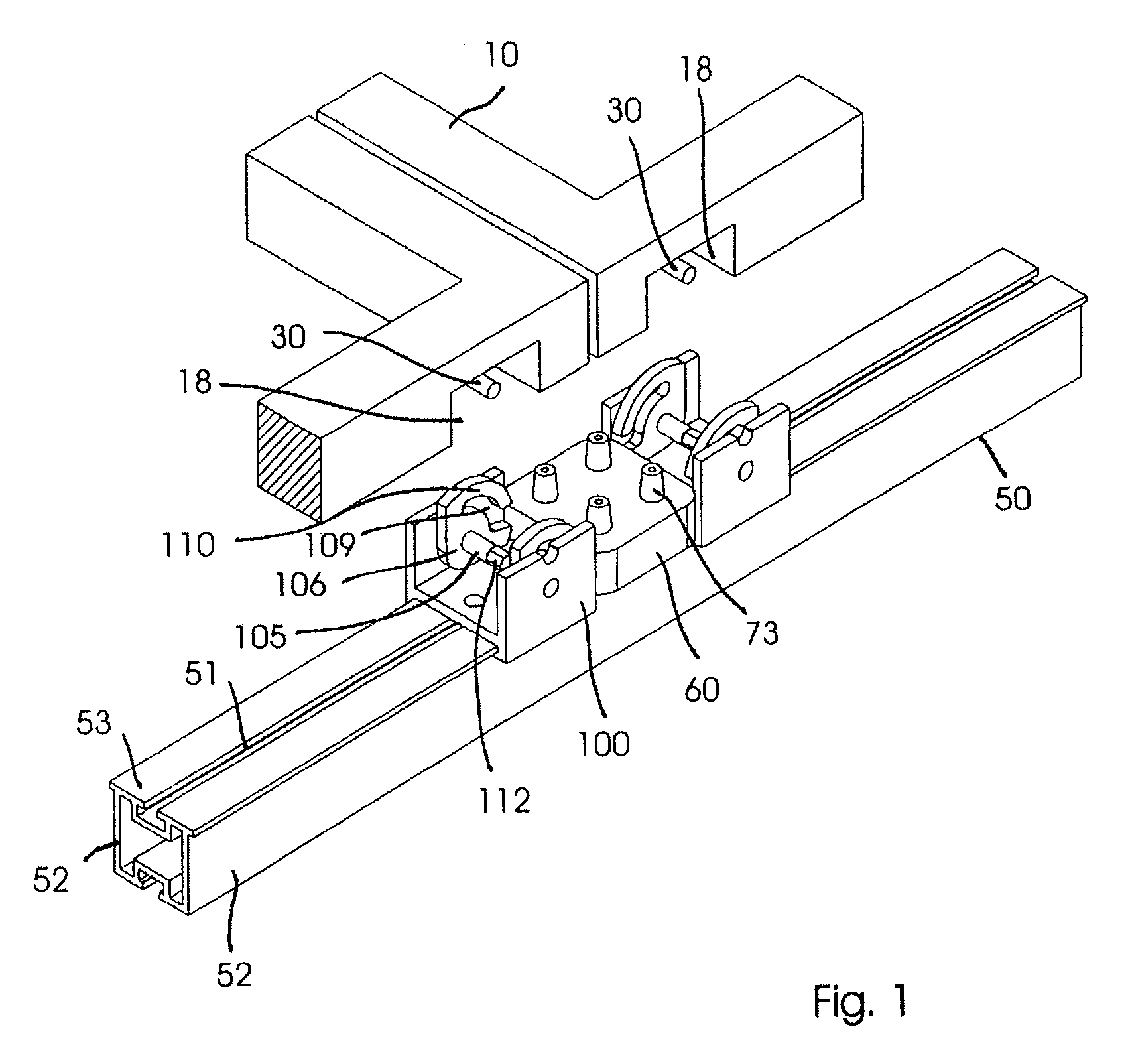
[0057]FIG. 1 shows in a perspective exploded view a detail of a solar power system according to the present invention. This comprises a plurality of parallel mounting supports 50 arranged at a distance to each other or in a frame-like manner on which are mounted holding elements 100 and double bridges 60 serving as electric connecting elements. In each case, four holding elements 100 secure a photovoltaic module by positive fitting latching or interlocking of holding studs 30 disposed in the corner regions of the holding frame, as described below. On the interlocking of the holding studs 30, contact plugs or contact sockets arranged in corner regions on the underside of the holding frame are simultaneously plugged together with the associated contact sockets or contact plugs 73 of the double bridge 60 by means of which electric contacting for the interconnection of two adjacent photovoltaic modules is achieved.

[0058]According to FIG. 1, the mounting support 50 is embodied as an endl...

second embodiment

[0069]FIG. 5 shows a mounting support embodied as an endless profile with a connecting element according to the present invention. According to FIG. 5, the mounting support 50 embodied as an endless profile is encompassed in a clamp-like manner by a connecting element 60 with a U-shaped cross section. In the middle of the connecting element 60, the two side walls 62 protruding perpendicularly from the base 63 form a central accommodating element 61 extending in the longitudinal direction for accommodating the mounting support 50 in the longitudinal direction. In assembled condition, the side walls 62 lie directly on side walls of the mounting support 50. Protruding from the side walls 62 are latching pins 65 which are prestressed inward by means of pressure springs. In assembled condition, the tips of the latching pins 65 protrude into the T-groove 51 of the associated mounting support 50 in order to latch the position of the connecting element 60 relative to the mounting support 50...


PUM


Abstract

The invention relates to a solar power system comprising a plurality of mounting supports (50), a plurality of photovoltaic modules (1) mounted on the mounting supports (50), a plurality of holding elements (60, 100) for holding the photovoltaic modules (1) on the mounting supports (50) and a plurality of electric connecting elements (60) for electrically interconnecting the photovoltaic modules, and wherein the electric connecting elements (60) comprise two electrically contacting connecting plugs (40-43, 70-74) which can be plugged together and which are designed such that they are plugged together with the mounting movement of the respective photovoltaic module when mounting it on a mounting support (50).According to the invention the photovoltaic modules (1) are each bordered at the edge at least in sections by a holding frame (10) made of a plastic, wherein mechanical connecting means (30) and at least one connecting plug (40-43, 70-74) are integrated in the holding frame (10) and wherein the mechanical connecting means (30) each interact with an associated holding element (60, 100) in a positive fitting manner.

Description

[0001]The present application claims the priorities of German patent applications DE 10 2005 050 884.7 “Photovoltaic Module, Method for its Production and System comprising a Plurality of Photovoltaic Modules”, filed on 21 Oct. 2005, and DE 10 2005 050 883.9 “Solar power system comprising a plurality of photovoltaic modules”, filed on 21 Oct. 2005, and their content is hereby expressly incorporated by reference into the present application.FIELD OF THE INVENTION[0002]The present invention relates generally to photovoltaic modules with a holding frame, for example to be used to design roof coverings or facade surfaces and relates in particular to a solar power system comprising a plurality of photovoltaic modules.BACKGROUND OF THE INVENTION[0003]Photovoltaic modules of the aforementioned kind convert radiation energy into electric energy. To satisfy the diverse requirement for the construction of solar systems, the solar cells are embedded in a mixture of numerous materials and compo...

Claims


Application Information

Patent Timeline
Patent Type & Authority Applications(United States)
IPC IPC(8): H01L31/042
CPCE04F13/0803F24J2/5211F24J2/5254F24J2002/4665F24J2002/5215F24J2002/5226H02S20/23Y02B10/12Y02E10/47Y02E10/50F24J2002/5288H02S20/00H01L31/048H02S30/10H02S40/32H02S40/34H02S40/36H02S20/20F24S25/632F24S2025/018F24S25/20F24S2025/807F24S2025/801F24S2025/6004Y02B10/10
Inventor KAMP, MICHAEL VIKTORREWIG, THOMASDIEFENBACH, KARL HEINZTIBITANZL, JOHANNES
Owner SYSTAIC
Why Eureka
Try Eureka