All-terrain powered vehicle and method of steering
Inactive Publication Date: 2008-10-23
HUES PETER JAMES
View PDF42 Cites 9 Cited by
Summary
Abstract
Description
Claims
Application Information
AI Technical Summary
This helps you quickly interpret patents by identifying the three key elements:
Problems solved by technology
Method used
Benefits of technology
[0015]As such, those skilled in the art will appreciate that the conception, upon which disclosure is based, may readily be utilized as a basis for designing other structures, methods, and systems for carrying out the several purposes of the present invention. It is important, therefore, that the claims be regarded as including such equivalent constructions insofar as they do not depart from the spirit and scope of the present invention.
[0016]Further, the purpose of the foregoing Abstract is to enable the U.S
Problems solved by technology
All of these three vehicles perform poorly when faced with steep slopes or deep powder.
With the rider's weight supported mostly or entirely by the board, their tracks tend to dig out snow in less than ideal conditions, thereby loosing traction.
The '959, '540, and '186 vehicles rely partially or fully upon heavily modified snowboards for turning and stability; however, these modifications (which include stiffening the board with one or more attachment plates and removing the tail and some of the rear portions of the board or removing a large section of the board and substituting the same with a tracked device while adding an angled region to the board) substantially degrade the turning ability of the board by reducing the effective edge length, increasing the rigidity, and reducing or eliminating the camber of the board.
With the power units of the '959 and '540 vehicles being flexibly mounted to the rear of the device, jumping is not recommended due to the potential for the power unit to become damaged upon landing or to cause injury to the user in the case of a fall.
However, with rigid, predominately vertical members in
Method used
Image
Click on the blue label to locate the original text in one second.
Reading with bidirectional positioning of images and text.
Examples
Embodiment Construction
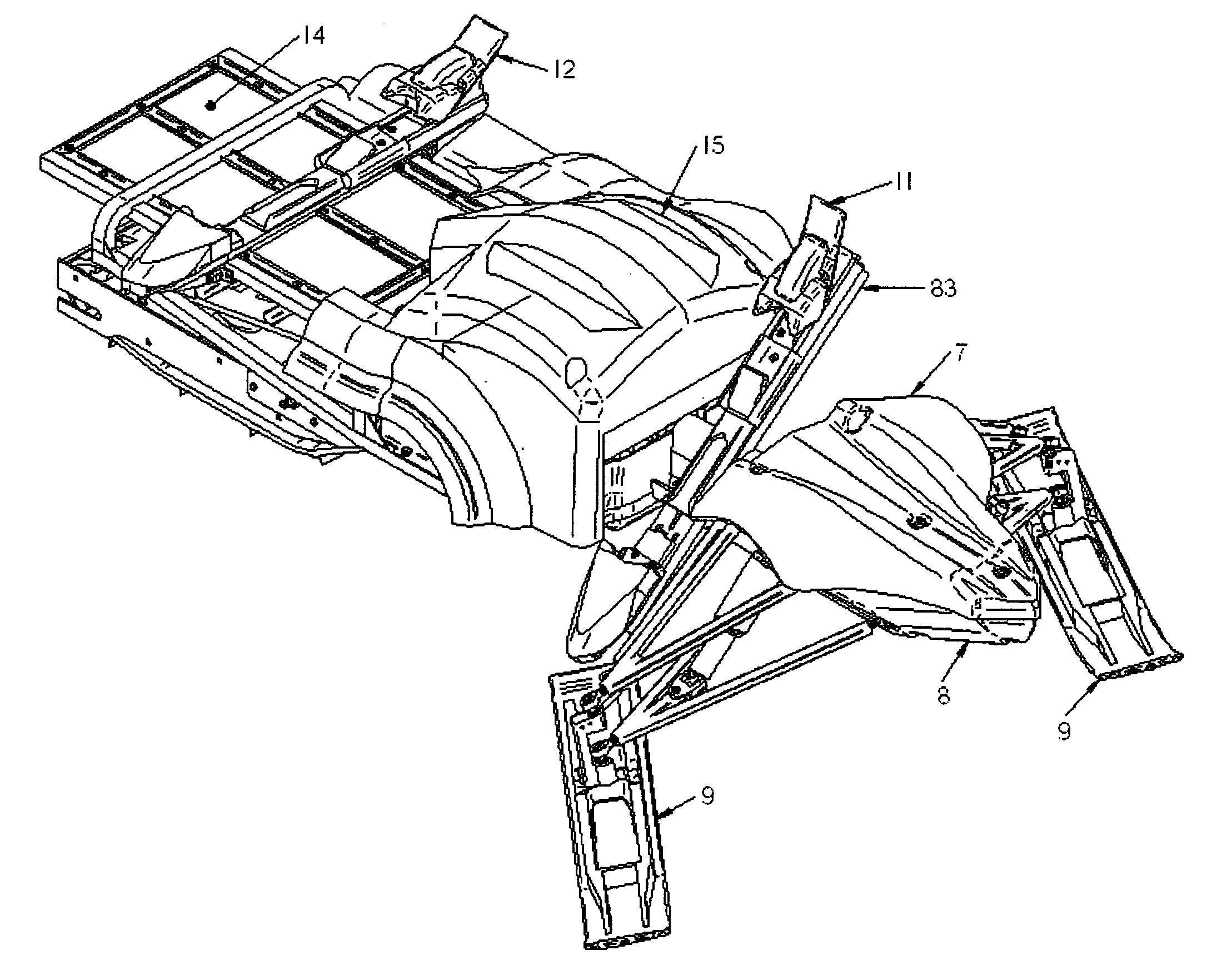
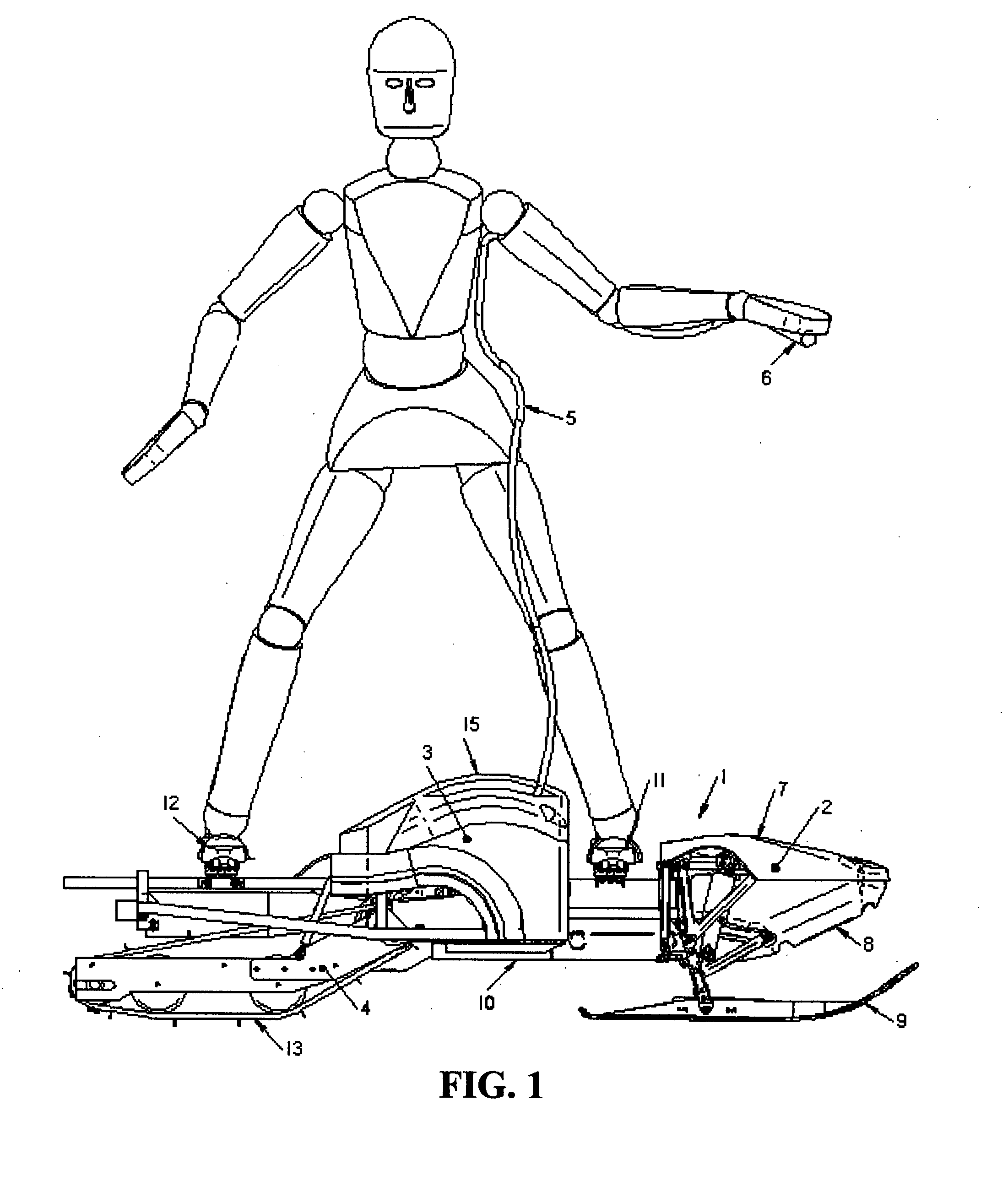
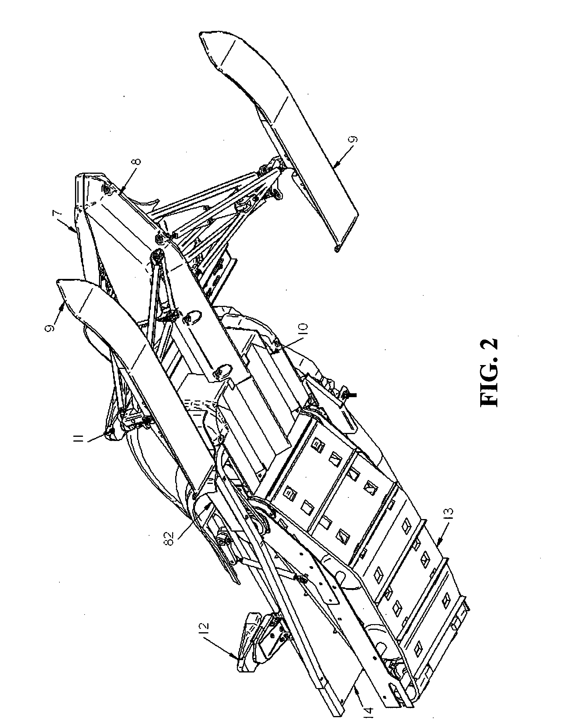
[0032]Referring now to the drawings, wherein like reference numerals designate identical or corresponding parts throughout the different views, several embodiments of the disclosed invention will be described. A powered vehicle 1 in accordance with the disclosed invention is shown schematically in FIGS. 1-4. It should be noted that all figures provided herein are simply illustrations of the invention and have not been drawn to scale. FIG. 1 illustrates a side view of the powered vehicle 1 in accordance with an embodiment of the present invention, FIG. 2 illustrates a perspective view of an underside of the powered vehicle 1 of FIG. 1 with body work, FIG. 3 illustrates a perspective view of a top of the powered vehicle 1 of FIG. 1 with body work, and FIG. 4 illustrates a detail perspective view showing a steering mechanism of the powered vehicle 1 of FIG. 1.
[0033]As illustrated in FIG. 1, the powered vehicle 1 includes a front portion 2 having a front fender 7, a power unit 3 enclose...
PUM
Abstract
A steering mechanism for a recreational vehicle includes a foot support and a steering device connected to the foot support, the steering device being moved by a motion of the foot support. A recreational vehicle is also disclosed that includes a front portion, a body connected to the front portion, a track mechanism disposed in the body, a steering mechanism disposed in the front portion, and a foot support disposed between the front portion and the body, the steering mechanism being steered by a motion of the foot support. A method of steering the recreational vehicle is also disclosed.
Description
BACKGROUND OF THE INVENTION[0001]1. Field of the Invention[0002]The present invention relates to a recreational vehicle and, more particularly, to an all-terrain, powered vehicle with foot-driven steering and to a method of steering related thereto.[0003]2. Description of the Related Art[0004]There exist many powered units that attempt to emulate gravity-driven recreational devices so as to extent their range of operation and to eliminate the need to pay expensive fees for entertainment. Consider, for example, but not as a limitation of the invention disclosed herein, motorized sled- or ski-type vehicles disclosed in U.S. Pat. Nos. 4,307,788 and 5,568,840, and motorized snowboards disclosed in U.S. Pat. Nos. 6,725,959, 6,698,540, 6,435,290 and 5,662,186, to name a few.[0005]Each of the '540, '959, and '186 patents depicts a motorized ski vehicle having a power-driven endless track at the rear of the vehicle and a modified snowboard at the front. The user faces in the direction of tr...
Claims
Application Information
Patent Timeline
Application Date:The date an application was filed.
Publication Date:The date a patent or application was officially published.
First Publication Date:The earliest publication date of a patent with the same application number.
Issue Date:Publication date of the patent grant document.
PCT Entry Date:The Entry date of PCT National Phase.
Estimated Expiry Date:The statutory expiry date of a patent right according to the Patent Law, and it is the longest term of protection that the patent right can achieve without the termination of the patent right due to other reasons(Term extension factor has been taken into account ).
Invalid Date:Actual expiry date is based on effective date or publication date of legal transaction data of invalid patent.