Synchronized multiple drive wire feed welding system and method

a welding system and wire feed technology, applied in welding/cutting media/materials, welding apparatus, manufacturing tools, etc., can solve the problems of welding wire passing compression or tension, wire jamming, and welding more difficult or impossibl

Active Publication Date: 2008-10-23
ILLINOIS TOOL WORKS INC
View PDF13 Cites 77 Cited by
  • Summary
  • Abstract
  • Description
  • Claims
  • Application Information

AI Technical Summary

Problems solved by technology

Unfortunately, the multiple wire drives are often out-of-synchronization, thereby causing compression or tension in the welding wire passing between the multiple wire drives.
Unfortunately, the coiling of the wire can cause random directional changes in the wire feed trajectory, thereby making welding more difficult or impossible.
If the columnar strength of the wire is exceeded while in compression, then the welding wire can buckle causing a wire jam and failure of the system.
If the welding wire is in tension between the multiple wire drives, then the welding wire may become deformed due to compaction, stretching, or shaving.
Again, the wire deformation can cause random directional changes in the wire feed trajectory, thereby making welding more difficult or impossible.
Excessive tension in the welding wire can also cause drive roll slippage in each of the multiple wire drives, thereby causing inconsistencies in the amount of wire delivered to the welding arc.
The wire tension can also cause failure of the welding wire drives, for example, due to excessive motor current and excessive wear of the gears and bearings.
Unfortunately, these problems with tension and compression in the welding wire are currently addressed by replacing the welding wire drives or separately calibrating the drives, which is both costly and time consuming.
In addition, these solutions may require special equipment to identify and resolve the problem.

Method used


Image

  • Synchronized multiple drive wire feed welding system and method
  • Synchronized multiple drive wire feed welding system and method
  • Synchronized multiple drive wire feed welding system and method

Examples


Embodiment Construction

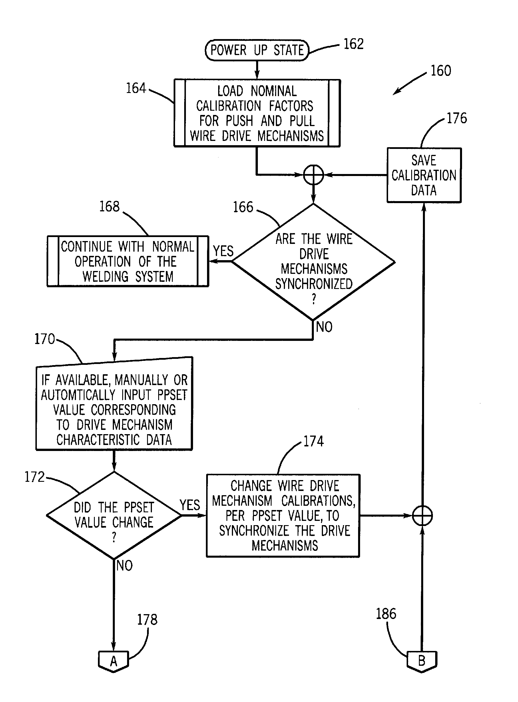
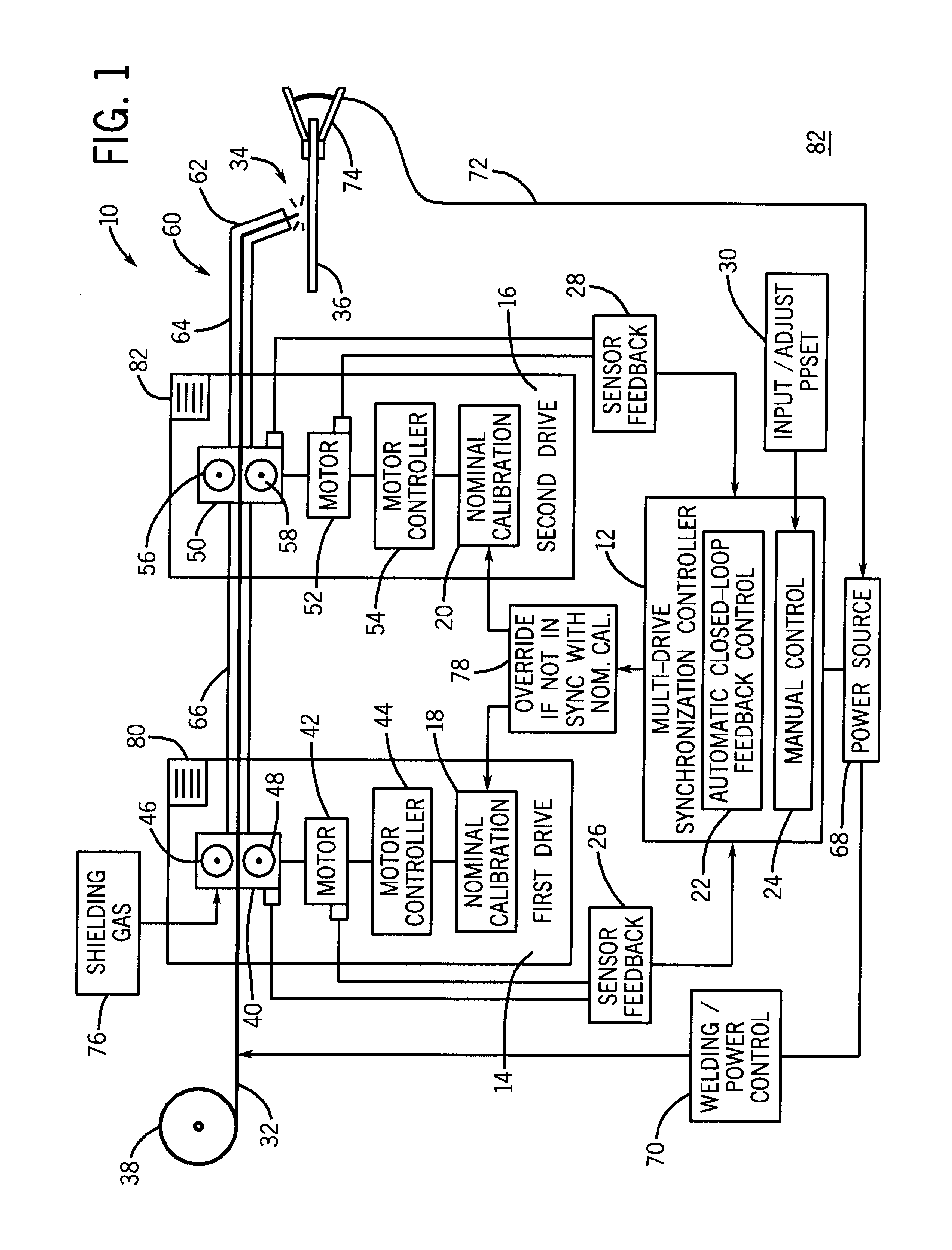
[0011]As discussed in detail below, the present embodiments relate to a unique and simple technique for synchronizing a plurality of welding wire drives in a welding system. Specifically, the multiple wire drives are used with nominal calibration data unless the drives are not in synchronization with one another. For example, if one or more of the wire drives is functioning outside of normal tolerance levels, then the present embodiments override the nominal calibration data of that particular drive to ensure synchronization with the other drive in the system. Thus, the out-of-sync drive is not discarded, replaced, or calibrated with special equipment.

[0012]Instead, in certain embodiments, a single control parameter may be used to control the speed, torque, and other parameters of all wire drives in the system, thereby ensuring synchronization of the drives with one another. For example, a user may increase, decrease, or generally input the control parameter via a keypad, a rotatabl...


PUM

PropertyMeasurementUnit
tensionaaaaaaaaaa
speedaaaaaaaaaa
torqueaaaaaaaaaa

Abstract

A welding system, in certain embodiments, includes a synchronization controller configured to override a first nominal calibration of a first wire drive, or a second nominal calibration of a second wire drive, or both, in response to a tension condition or a compression condition of a welding wire feeding between the first and second wire drives. A welding system, in other embodiments, includes a welding wire drive having a motor, a controller, a nominal calibration, and a multi-drive synchronization parameter. The multi-drive synchronization parameter may be configured to control speed, or torque, or both, of multiple drives including the welding wire drive to facilitate synchronization of the multiple drives.

Description

BACKGROUND[0001]The invention relates generally to welding systems and, more specifically, to multiple drives in a wire feed welding system.[0002]Welding systems sometimes include multiple wire drives to feed a welding wire to a torch. Unfortunately, the multiple wire drives are often out-of-synchronization, thereby causing compression or tension in the welding wire passing between the multiple wire drives. If the welding wire is in compression between the multiple wire drives, then the welding wire can buckle or coil like a spring. Unfortunately, the coiling of the wire can cause random directional changes in the wire feed trajectory, thereby making welding more difficult or impossible. If the columnar strength of the wire is exceeded while in compression, then the welding wire can buckle causing a wire jam and failure of the system. If the welding wire is in tension between the multiple wire drives, then the welding wire may become deformed due to compaction, stretching, or shavin...

Claims


Application Information

Patent Timeline
Patent Type & Authority Applications(United States)
IPC IPC(8): B23K9/10
CPCB23K9/124B23K9/125B23K9/1336
Inventor KAUFMAN, CHARLES L.SPEILMAN, BRANDON J
Owner ILLINOIS TOOL WORKS INC
Why Eureka
Try Eureka