Optical Pickup Actuator and Optical Scanning Device

a technology of optical scanning device and actuator, which is applied in the direction of data recording, instruments, disposition/mounting of heads, etc., can solve the problems of not being able to accommodate a thin actuator or a slim line in the coil system, and achieve the effect of improving the scanning performance of the optical scanning devi

Inactive Publication Date: 2008-10-23
KONINKLIJKE PHILIPS ELECTRONICS NV
View PDF4 Cites 0 Cited by
  • Summary
  • Abstract
  • Description
  • Claims
  • Application Information

AI Technical Summary

Benefits of technology

[0009]Having the tracking coil system located opposite to the beam entrance side reduces the amount of coils and magnets at that side allowing room for a radiation beam to enter the optical pickup actuator.
[0028]Application of a second lenssystem makes it possible to adapt the optical pickup actuator for scanning a second, third or even fourth type of optical record carrier. The lenssystem may for example be designed for scanning a CD and / or DVD and the second lenssystem may be designed for scanning a BD. Also other combinations are possible such as, for example, the lenssystem being designed for scanning a CD and / or HDDVD and the second lenssystem being designed for scanning a DVD and / or BD, or vice versa.

Problems solved by technology

However the arrangement of the coil systems does not allow for a slim line or thin actuator as the height and location of the coils determine lowest entrance position of for a radiation beam to enter the actuator.

Method used


Image

  • Optical Pickup Actuator and Optical Scanning Device
  • Optical Pickup Actuator and Optical Scanning Device
  • Optical Pickup Actuator and Optical Scanning Device

Examples


Embodiment Construction

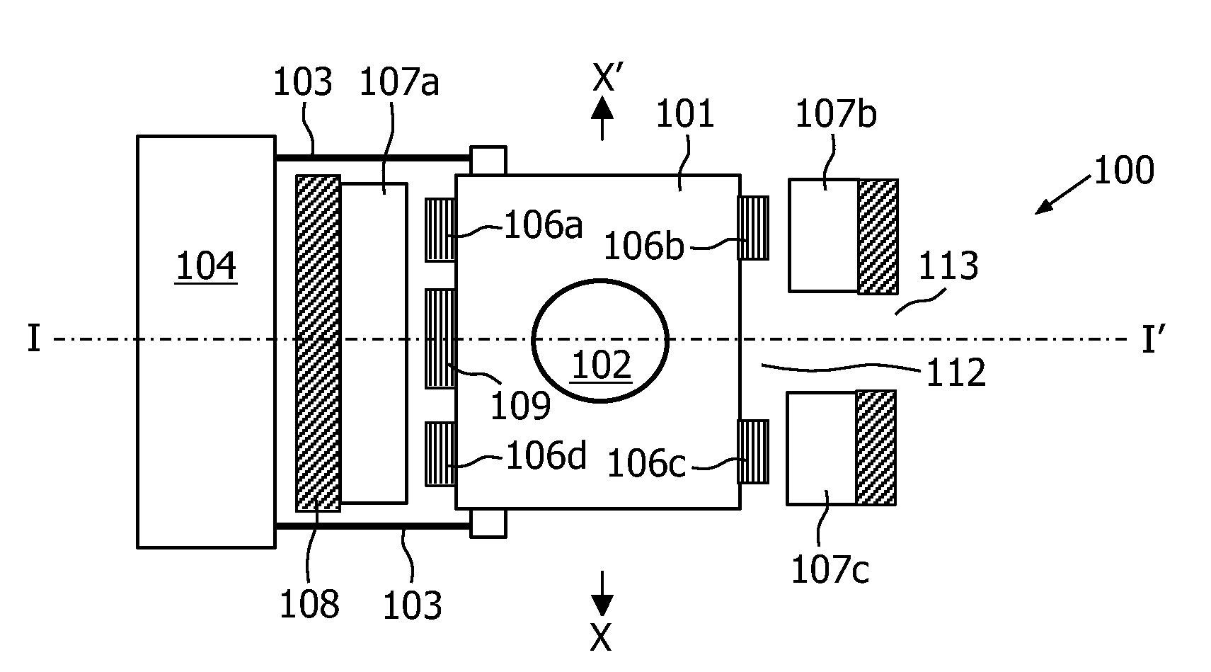
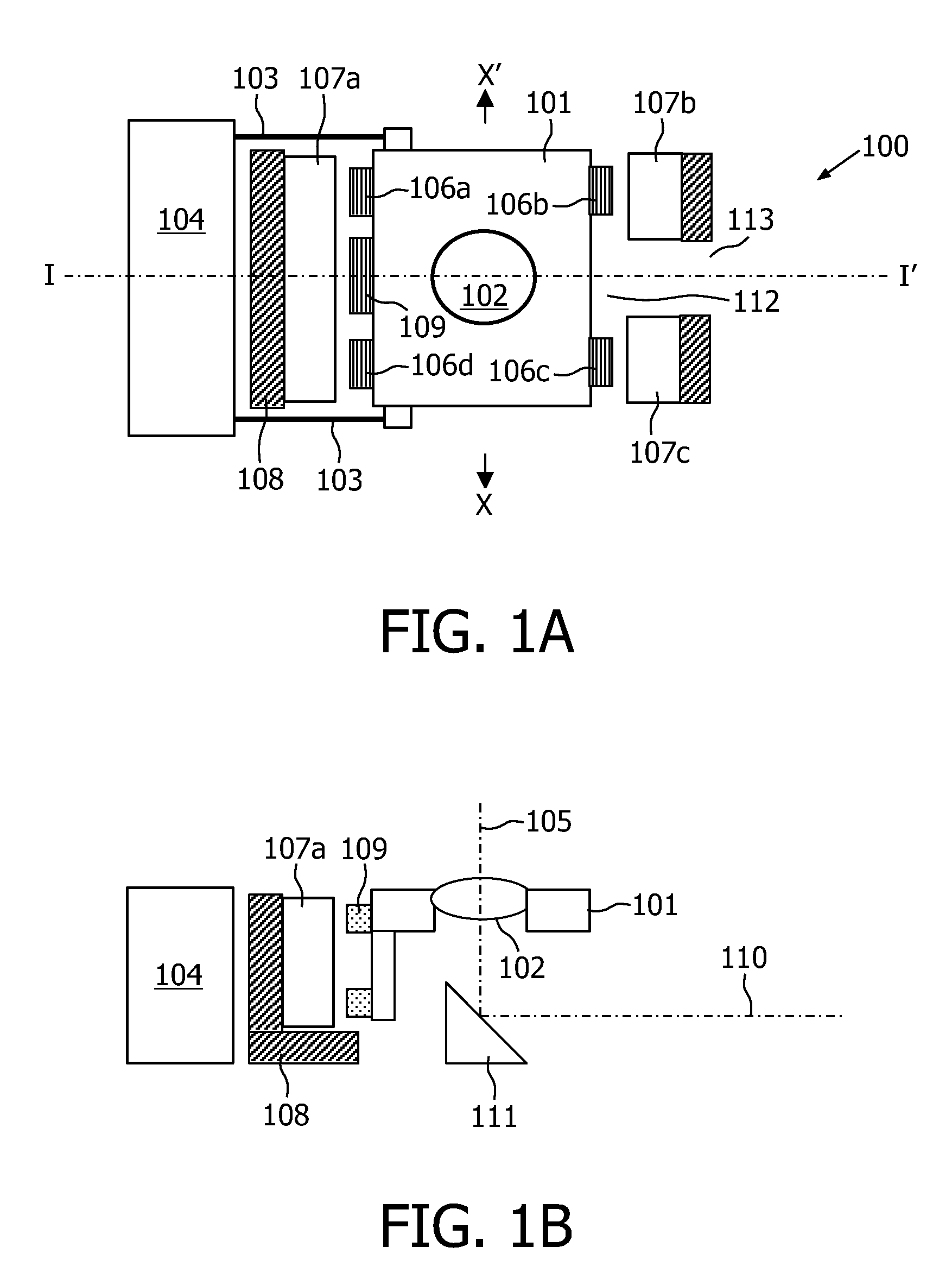
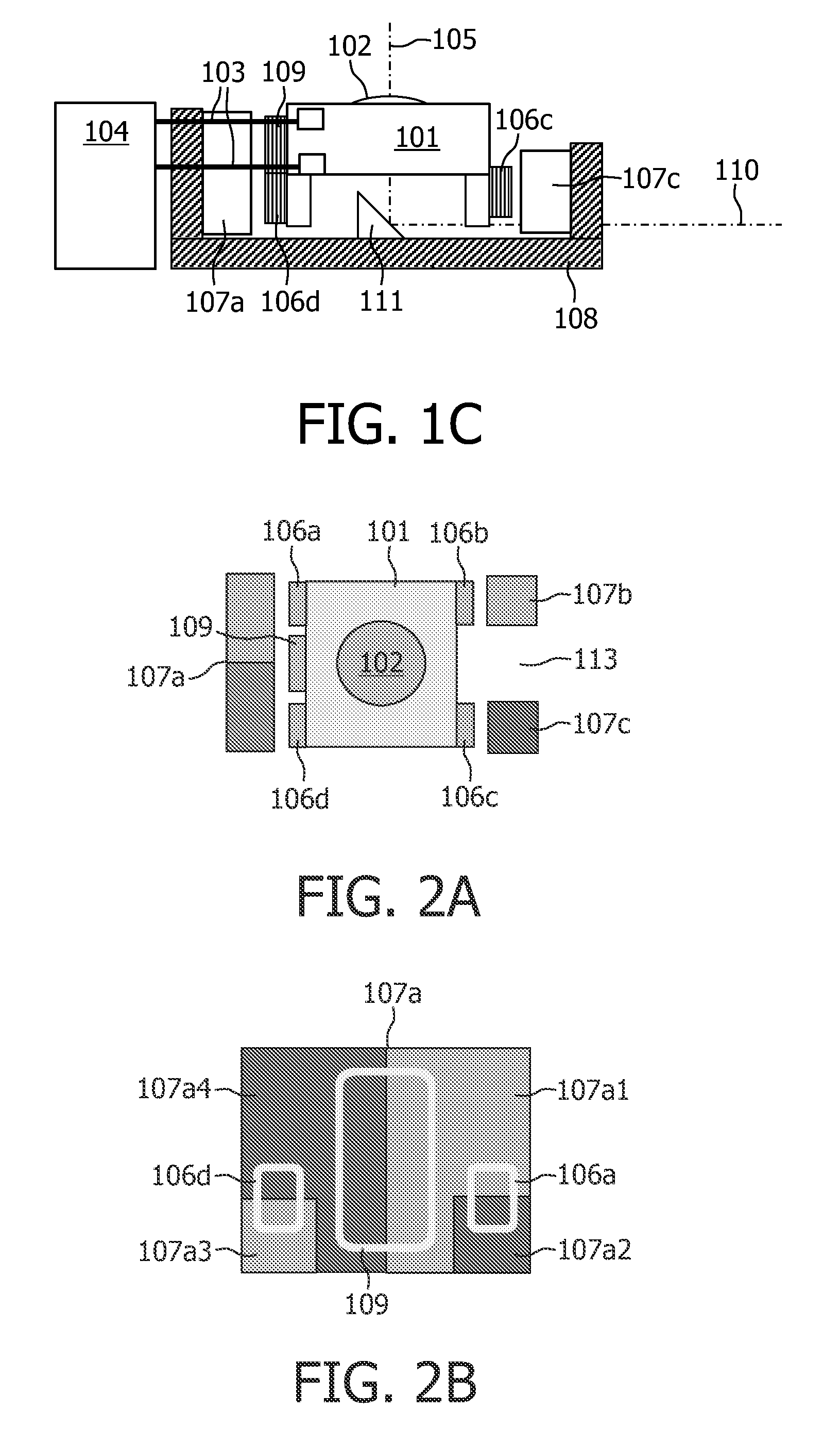
[0039]FIG. 1 schematically shows various views of an optical pickup actuator 100 according to the invention. The optical pickup actuator 100 will in the following for convenience be referred to as ‘actuator’. With reference to FIGS. 1A, 1B and 1C, a lens holder 101 having a lenssystem 102, is suspended from a connecting block 104 by a suspension means 103. This suspension means may, for example, comprise of suspension beams such as metal elastic rods. In FIGS. 1A, 1B and 1C the suspension means are shown as four metal elastic rods 103 that extend transversely to the optical axis 105 of the lenssystem (see FIG. 1B). The lenssystem 102 may be, for example, a single element objective lens or a multi-element objective lens.

[0040]One side of each elastic rod is fixed to the lensholder and the other side of the elastic rod is fixed to the connection block. It is noted that FIG. 1A and FIG. 1C only shows two of the four elastic rods 103. The use of the four elastic rods 103 enables the len...


PUM


Abstract

An optical pickup actuator for low building height includes a suspended lensholder (101) with a lenssystem (102), focusing (106a, 106b, 106c 106d) and tracking coils (109) and magnets (107a, 107b, 107c) for cooperation with the focusing and tracking coils. The focusing and tracking coils may be arranged for tilting the lensholder in the actuator. The lowest entrance position for a radiation beam to enter a beam entrance (113) at a side of the actuator is not determined by the height and location of the coils.

Description

FIELD OF THE INVENTION[0001]This invention relates to an optical pickup actuator comprising a lensholder having a lenssystem with an optical axis, the lensholder being suspended by a suspension means, a magnet system separated from said lensholder, a focusing coil system and a tracking coil system mounted to said lensholder, the lensholder having a beam entrance side substantially perpendicular to the optical axis for receiving a radiation beam.[0002]The invention also relates to an optical scanning device comprising an optical pickup actuator.BACKGROUND OF THE INVENTION[0003]Optical pickup actuators as well as optical read and / or write systems comprising an optical pickup actuator for scanning an optical record carrier such as a Compact Disc (CD) or Digital Versatile Disc (DVD) are known. For convenience an optical record carrier may in the following also be referred to as a disc, although also a card-shaped optical record carrier may be possible. Tracking and focusing coil systems...

Claims


Application Information

Patent Timeline
IPC IPC(8): G11B7/00
CPCG11B7/0933G11B7/0935G11B7/0956G11B2007/0006G11B7/08G11B7/085G11B7/09G11B7/095
Inventor VAN DER AA, MICHAEL ADRIANUS HENRICUSHEIJMANS, PETER MICHAEL SILVESTER MARIAVAN ROOIJ, JOHANNES ANTONIUSRAAYMAKERS, JEROEN ARNOLDUS LEONARDUS JOHANNES
Owner KONINKLIJKE PHILIPS ELECTRONICS NV
Why Eureka
Try Eureka