Radio Lan System, and Base Station and Terminal Station Thereof

a radio lan and base station technology, applied in the field of wireless lan systems and stations, can solve problems such as voice interruption, frame dropping, fuzzy images, etc., and achieve the effect of avoiding voice interruption, avoiding voice interruption, and avoiding voice interruption

Inactive Publication Date: 2008-10-23
PIONEER CORP
View PDF4 Cites 40 Cited by
  • Summary
  • Abstract
  • Description
  • Claims
  • Application Information

AI Technical Summary

Benefits of technology

[0010]The present invention has been achieved in light of the above-described issues. An object of the present invention is to provide, in a wireless LAN system including first communication mode and second communication mode, a wireless LAN system, and an access point and a station thereof. T

Problems solved by technology

For example, when carrying out transmission and reception of motion data, such as video data, in streaming via the wireless LAN, unless the transmis

Method used


Image

  • Radio Lan System, and Base Station and Terminal Station Thereof
  • Radio Lan System, and Base Station and Terminal Station Thereof
  • Radio Lan System, and Base Station and Terminal Station Thereof

Examples


first embodiment

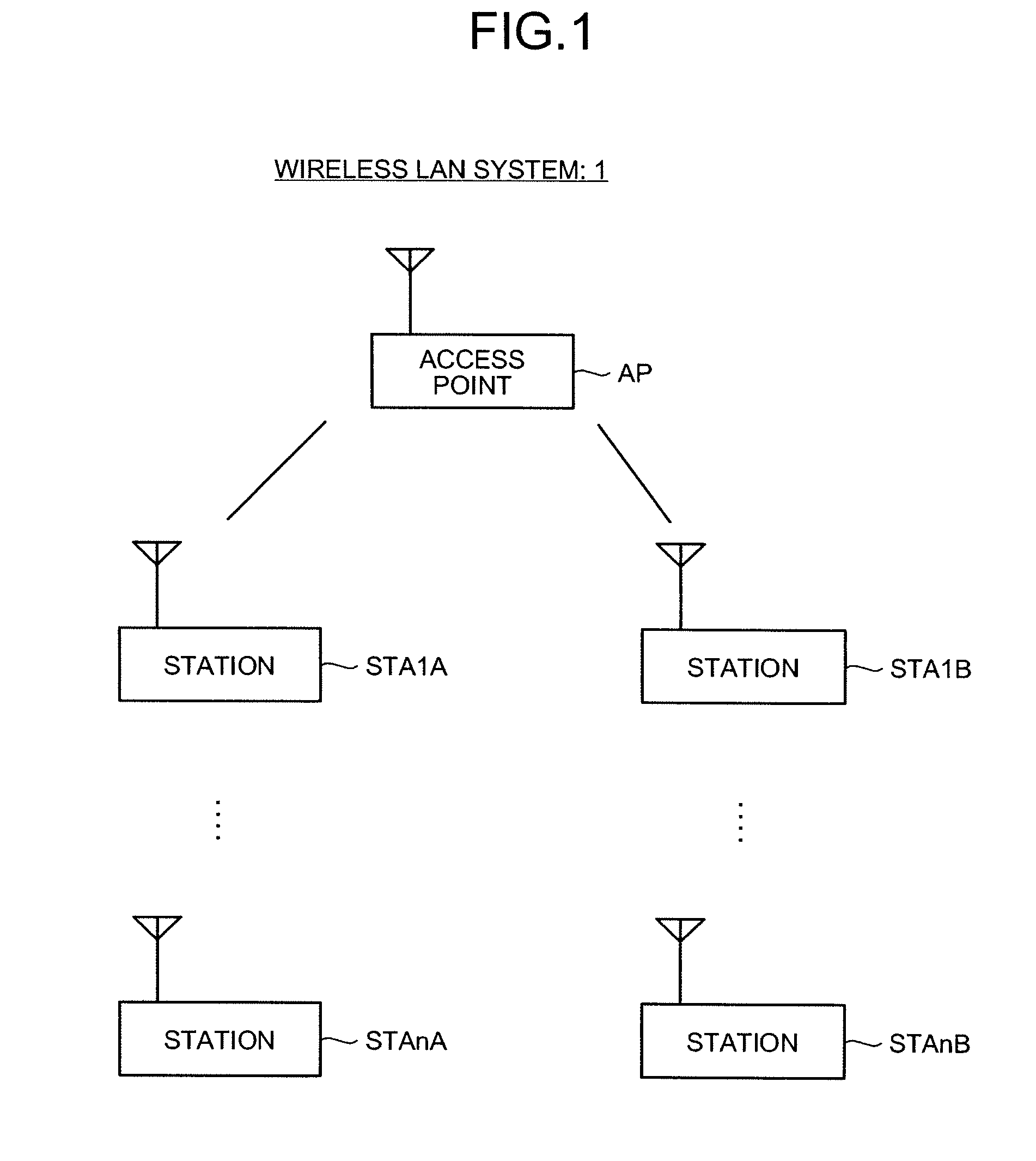
[0071]FIG. 1 is a diagram of an example of a system configuration of a wireless LAN system 1 according to a first embodiment. The wireless LAN system 1 shown in FIG. 1 is configured in compliance with IEEE802.11e. As shown in the diagram, the wireless LAN system 1 includes an access point AP and stations STA1A to STAnB. Hereafter, when the stations STA1A to STAnB are not particularly required to be differentiated, the stations STA1A to STAnB are referred to as an “STA”.

[0072]In the wireless LAN system 1, the AP takes into consideration a transmission request from the stations STA1A to STAnB and performs scheduling to grant a transmission right to the stations STA1A to STAnB. Based on the scheduling, the AP transmits a packet called QoS CF-Poll to the stations STA1A to STAnB. The QoS CF-Poll indicates that the transmission right is granted. The QoS CF-Poll includes information called Transmission Opportunity (TXOP) LIMIT. The TXOP LIMIT indicates a time period over which the transmis...

second embodiment

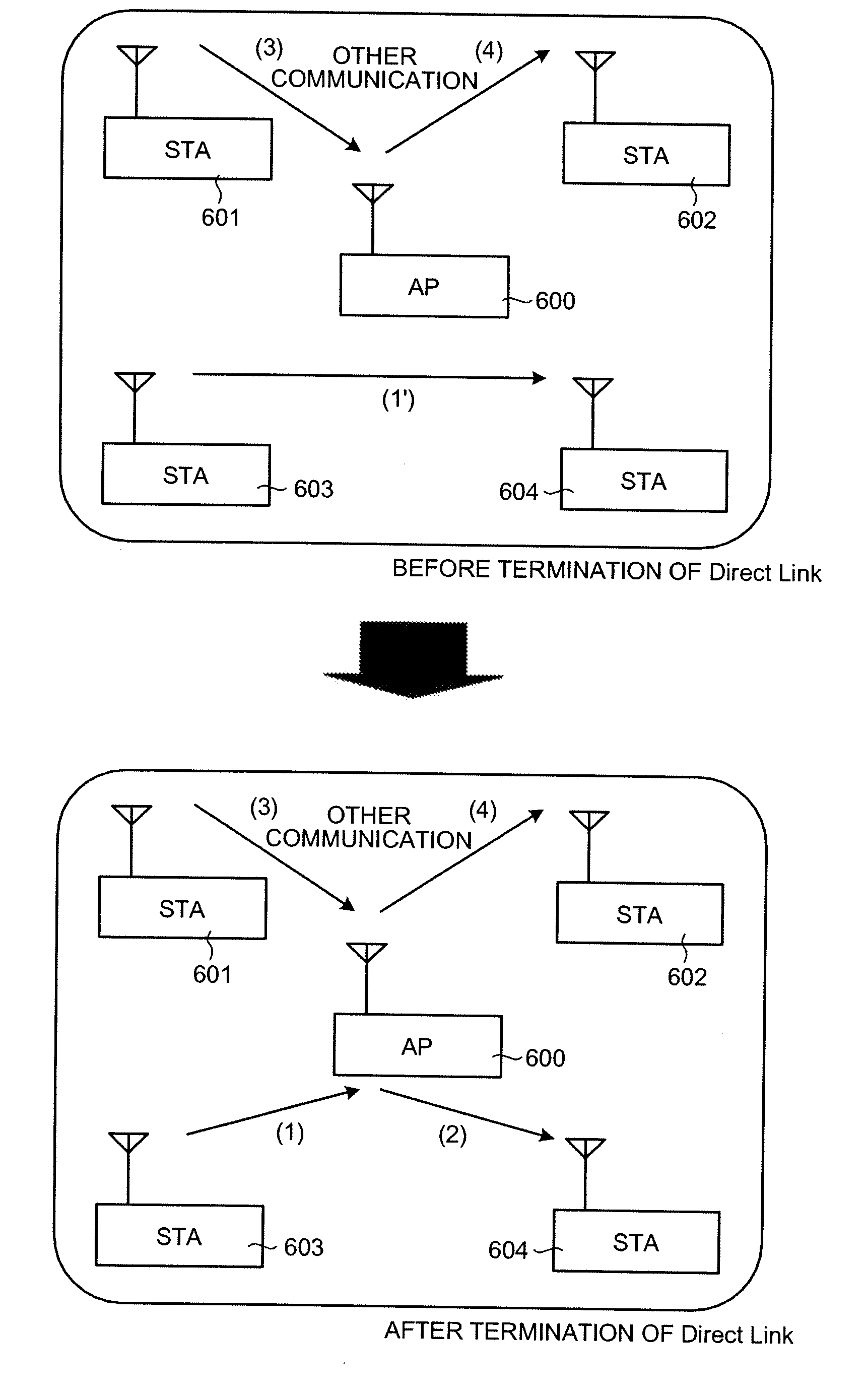
[0102]As described above, conventional AP and STA in compliance with IEEE802.11e are configured to reserve the bandwidth W as the QoS bandwidth when the Direct Link is used (see FIG. 16). On the other hand, although the AP and the STA of the present invention are configured in compliance with the IEEE802.11e, the bandwidth 2W that is twice the bandwidth W is reserved when the Direct Link is used. According to a second embodiment, a method of reserving the bandwidth 2W that is twice the bandwidth W as the QoS bandwidth when the Direct Link is used, even when the AP and the STA of the present invention and the conventional AP and STA are present in combination will be described. Hereafter, the conventional AP and STA in compliance with the IEEE802.11e are referred to as an AP and a STA performing a first operation. The AP and the STA of the present invention are referred to as an AP and a STA performing a second operation.

[0103]Various methods can be considered for a method of identif...


PUM


Abstract

A wireless LAN system that includes a plurality of stations and an access point, interconnected via a network, and supports QoS has infrastructure mode and a Direct Link. In the infrastructure mode, data communication is performed between stations STA via an access point AP. In the Direct Link, data communication is performed directly between the stations STA. The access point AP performs a process for reserving a bandwidth 2W that is twice a bandwidth W required when the Direct Link is used, in response to a QoS bandwidth reservation request when the Direct Link is used from a station STA. As a result, the QoS of data transfer can be ensured even when the Direct Link is terminated.

Description

TECHNICAL FIELD[0001]The present invention generally relates to a wireless LAN system and stations and an access point used in the wireless LAN system. The present invention more particularly relates to a wireless LAN system compatible with QoS and including a plurality of stations and an access point that are connected to each other via a network, and relates to stations and an access point for use in the wireless LAN system.BACKGROUND ART[0002]In computer networks, packet transmission and reception are carried out using a communication system called a packet communication system. Recently, demand for establishing a network using wireless communication is increasing in a household LAN (Local Area Network), for example. As compared with a wired LAN, the wireless LAN has such advantages that the installation of a wire such as a cable is not necessary and that the degree of freedom of moving a terminal connected to the LAN is high.[0003]The IEEE802.11 radio communication system (a sys...

Claims


Application Information

Patent Timeline
IPC IPC(8): H04Q7/00H04W72/04H04W84/12H04W92/10H04W92/18
CPCH04L12/5691H04L12/5695H04L47/728H04L47/788H04L47/824H04W28/24H04W84/12H04W88/06H04W92/18H04L47/70
Inventor ITO, YOICHI
Owner PIONEER CORP
Why Eureka
Try Eureka