Forced Air Heater Including On-Board Source of Electric Energy

a forced air heater and electric energy technology, applied in air heaters, lighting and heating apparatuses, heating types, etc., can solve the problems of increasing equipment, consuming even more electric energy for the operation of the igniter, and not being able to provide a conventional wall outl

Active Publication Date: 2008-10-23
ENERCO GROUP
View PDF3 Cites 38 Cited by
  • Summary
  • Abstract
  • Description
  • Claims
  • Application Information

AI Technical Summary

Problems solved by technology

The fan is often a heavy-duty, high output fan that consumes significant amounts of electric energy during operation thereof, and operation of the igniter consumes even more electric energy.
However, at locations where a new structure is being built a conventional wall outlet is typically not available, requiring the use of a portable generator to supply the electric energy until utility-generated electric energy becomes available.
However, the light stand adds to the equipment that must be transported to a jobsite, and a conventional wall outlet is usually not available during the initial stages of a new construction.
Even in instances when a conventional wall outlet is available, there are normally a limited number of electric devices that can be powered by the outlet at any given time.
Using adaptors to increase the number of available outlets into which an electrical device can be plugged can lead to excessive currents being drawn through an extension cord or other adaptor.
Thus, there are a limited number of electrical devices that can be simultaneously powered on a new construction jobsite at any given time.
This limitation is even greater when a wall outlet supplying utility-generated electricity is unavailable.
Forced-air heaters are also relatively bulky, and occupy a significant amount of storage space while not in use.
Attempts to store such a heater in an alternative orientation other than its intended operational orientation in which the heater is designed to be fired in order to conserve storage space results in the liquid fuel leaking out of the heater.
And although the fuel can be drained from the heater before storing it in an alternative orientation to minimize the leakage of fuel, such an option is time consuming, and is impractical for temporary storage on a daily basis.

Method used


Image

  • Forced Air Heater Including On-Board Source of Electric Energy
  • Forced Air Heater Including On-Board Source of Electric Energy
  • Forced Air Heater Including On-Board Source of Electric Energy

Examples


Embodiment Construction

[0024]Certain terminology is used herein for convenience only and is not to be taken as a limitation on the present invention. Relative language used herein is best understood with reference to the drawings, in which like numerals are used to identify like or similar items. Further, in the drawings, certain features may be shown in somewhat schematic form.

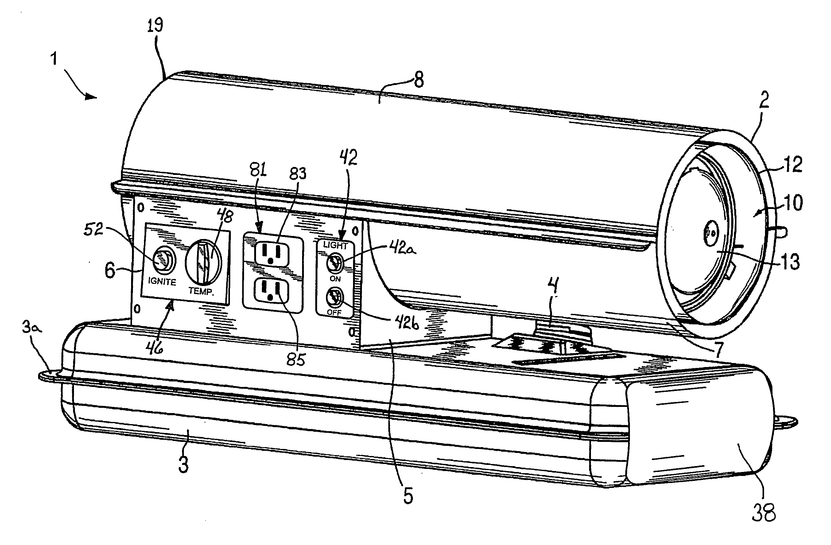
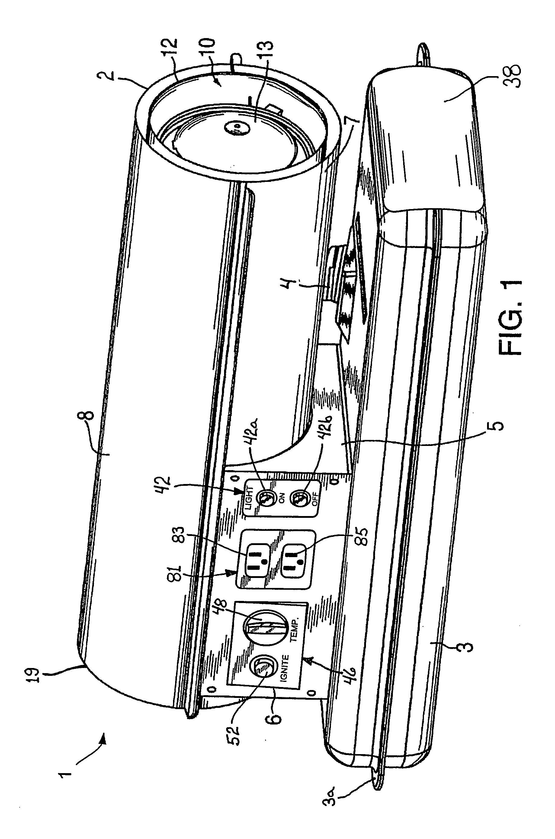
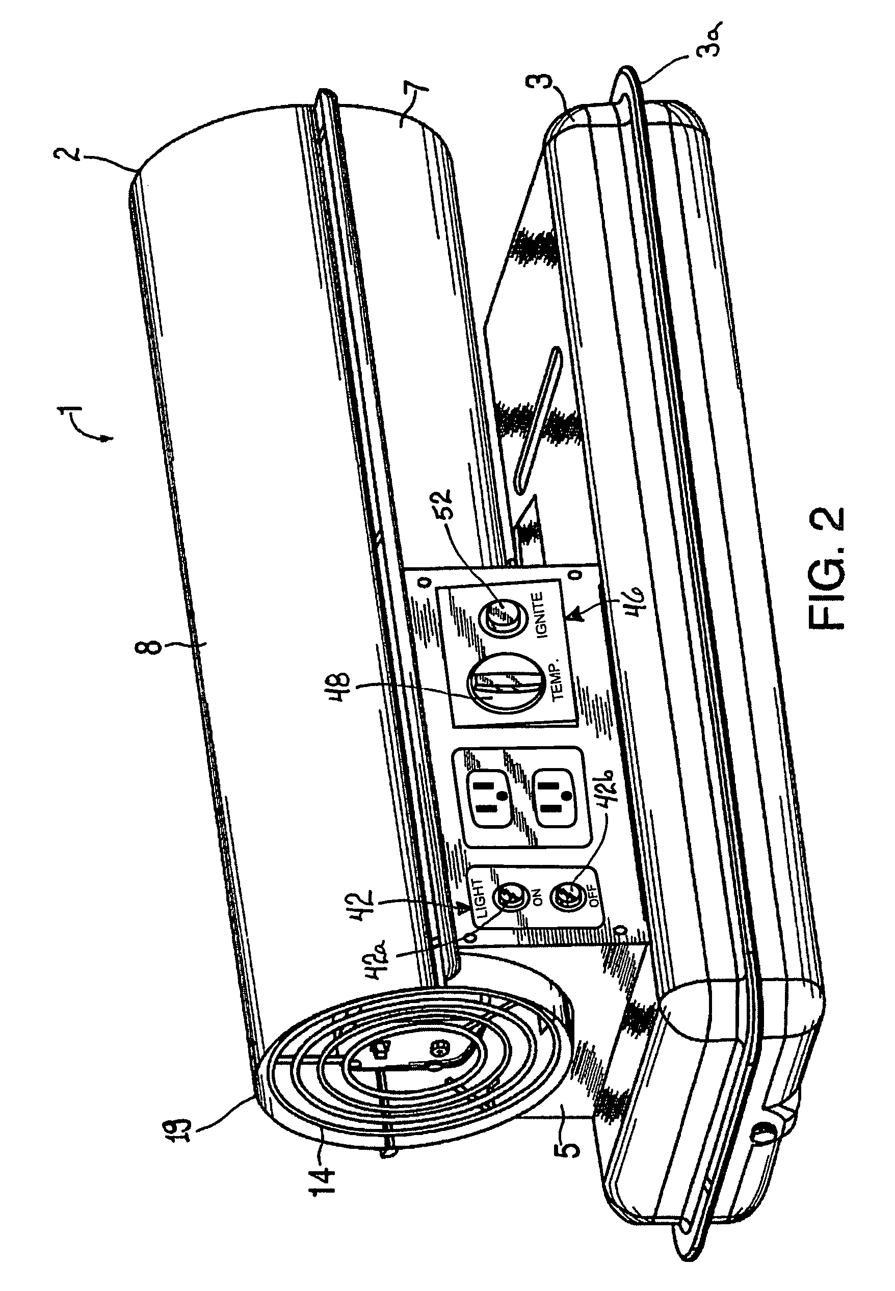
[0025]FIGS. 1 and 2 show illustrative embodiments of a forced-air heater 1, which generally includes a fuel tank 3, a support 5, a housing including upper and lower housing portions 8, 7, respectively, and a combustion chamber 10 including an inner cylinder 11 and an outer cylinder 12. Alternate embodiments include a housing formed as a singular, generally cylindrical shell. A semi-spherical shaped baffle 13 is provided adjacent to a discharge end 2 of the combustion chamber 10 and an intake guard 14 is provided adjacent to an air intake end 19 port of the forced-air heater 1.

[0026]The fuel tank 3 can optionally be formed as a sing...


PUM


Abstract

A forced-air heater having a self-contained on-board electric-power supply that allows the forced-air heater to operate without an external electric power source; a fuel tank; a combustion chamber; a support; a housing including upper and lower housing portions; a motorized fan that during operation draws in ambient air through an air intake and forces air into the combustion chamber.

Description

CROSS-REFERENCE TO RELATED APPLICATIONS[0001]This application claims priority to U.S. Ser. No. 60 / 874,427 entitled Forced Air Heater Including On-Board Source of Electric Energy, filed Dec. 12, 2006. All of the subject matter disclosed by U.S. Ser. No. 60 / 874,427 is hereby incorporated by reference into this application.STATEMENT REGARDING FEDERALLY SPONSORED RESEARCH OR DEVELOPMENT[0002]Not ApplicableTHE NAMES OF THE PARTIES TO A JOINT RESEARCH AGREEMENT[0003]Not ApplicableINCORPORATION-BY-REFERENCE OF MATERIAL SUBMITTED ON A COMPACT DISC[0004]Not ApplicableBACKGROUND OF THE INVENTION[0005]1. Field of the Invention[0006]This invention relates generally to portable forced-air heaters, and more particularly to portable forced-air heaters that derive at least a portion of their electric energy required for operation of the heaters, or an accessory thereof, from an on board source.[0007]2. Description of Related Art[0008]Fuel-fired portable heaters such as forced-air heaters are well k...

Claims


Application Information

Patent Timeline
Patent Type & Authority Applications(United States)
IPC IPC(8): F24H3/02
CPCY02B30/28F24H3/0488Y02B30/00
Inventor VANDRAK, BRIAN S.O'TOOLE, DENNIS
Owner ENERCO GROUP
Why Eureka
Try Eureka