
Atmosphere Purge-Port Connecting Device for Wafer Storage Container

a technology for connecting devices and wafer storage containers, which is applied in the directions of packaging under vacuum/special atmosphere, transportation and packaging, packaging, etc., can solve the problems of non-operation during opening/closing, possible leakage of atmosphere in the wafer carrier b, and non-operation of so as to reduce the time required and increase the purge gas flow rate

Inactive Publication Date: 2008-10-23
RIGHT MFG
View PDF5 Cites 40 Cited by
  • Summary
  • Abstract
  • Description
  • Claims
  • Application Information

AI Technical Summary

Benefits of technology

[0026]An object of the present invention is to provide a connecting device that allows stabilization of the wafer carrier and implementation of purging operation in a short time.
[0036]According to the present invention, the gas inlet provided to the atmosphere purge port for purging the atmosphere in the wafer storage container and the communication port formed in the base are brought into close contact with each other by the close-contact mechanism. Therefore, even if the separating force due to the flow rate of purge gas occurs in the wafer storage container, the connecting device does not separate from the wafer storage container to stabilize the position of the wafer storage container. Moreover, the flow rate of purge gas can be increased to reduce the time required to purge the atmosphere in the wafer storage container.

Problems solved by technology

Moreover, although the carrier door 13 includes a packing, not shown, for maintaining the hermeticity of the wafer carrier 10, the hermeticity ensured by the packing is not perfect, thereby causing possible leakage of the atmosphere in the wafer carrier 10 to the outside.
Furthermore, when a photoresist is applied on the surface of the wafers 1, an organic solvent evaporated from the photoresist diffuses inside the wafer carrier 10, causing possible organic contamination of the atmosphere.
This may cause vertical displacement of the position of the carrier door 13 provided to the wafer carrier 10, leading to occurrence of a problem of non-operation during opening / closing, etc.
With the wafer carrier of Patent Document 1, however, the nonuse of the existing purge port results in modification of the configuration of the wafer carrier, leading to possible occurrence of a cost increase.
Moreover, with the wafer carrier, the lid provided to the gas inlet undergoes the pressure due to the flow rate of purge gas, and is thus pushed up from below to above, leading to possible occurrence of positional instability.

Method used


Image

  • Atmosphere Purge-Port Connecting Device for Wafer Storage Container
  • Atmosphere Purge-Port Connecting Device for Wafer Storage Container
  • Atmosphere Purge-Port Connecting Device for Wafer Storage Container

Examples


embodiment 1

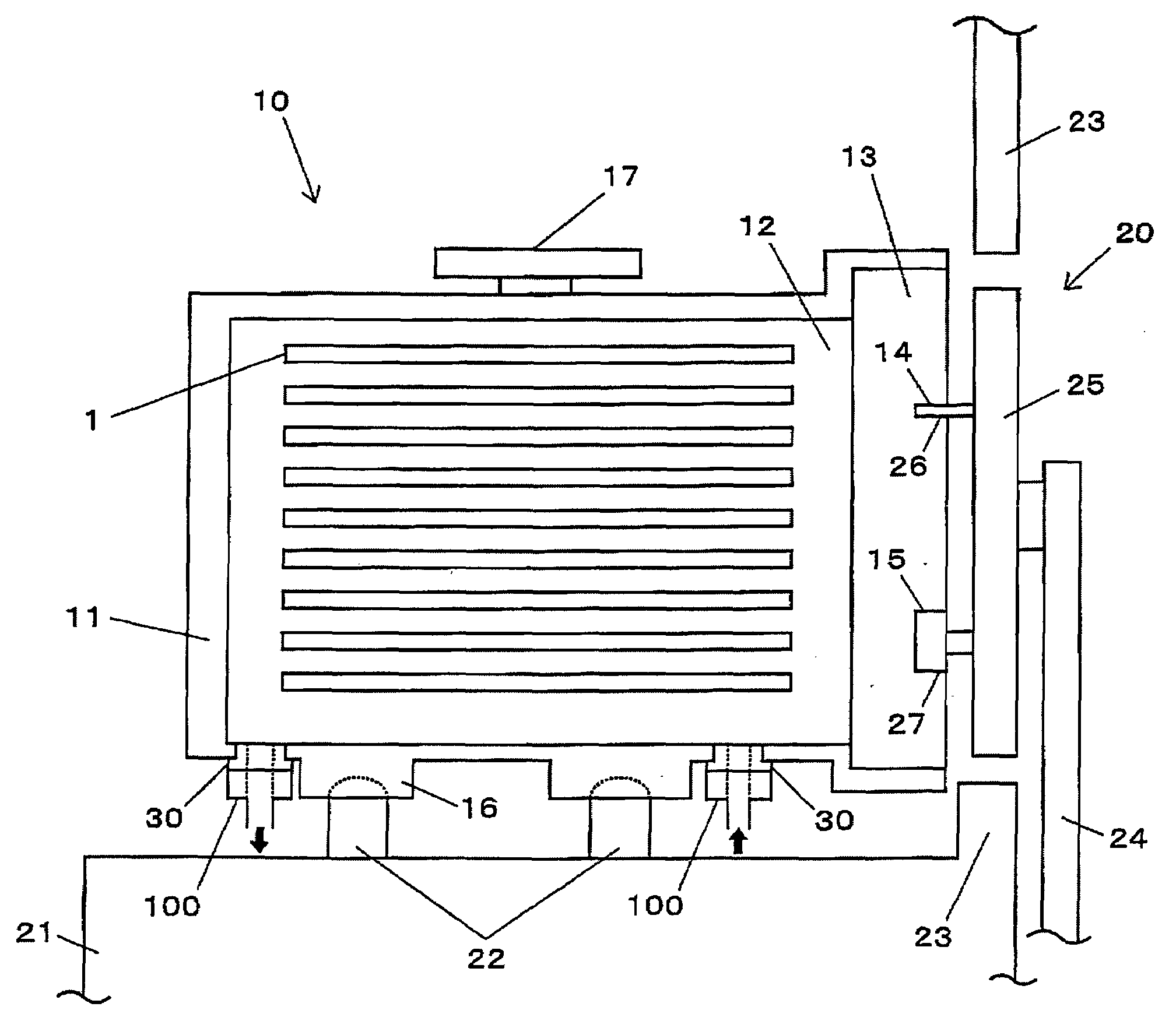
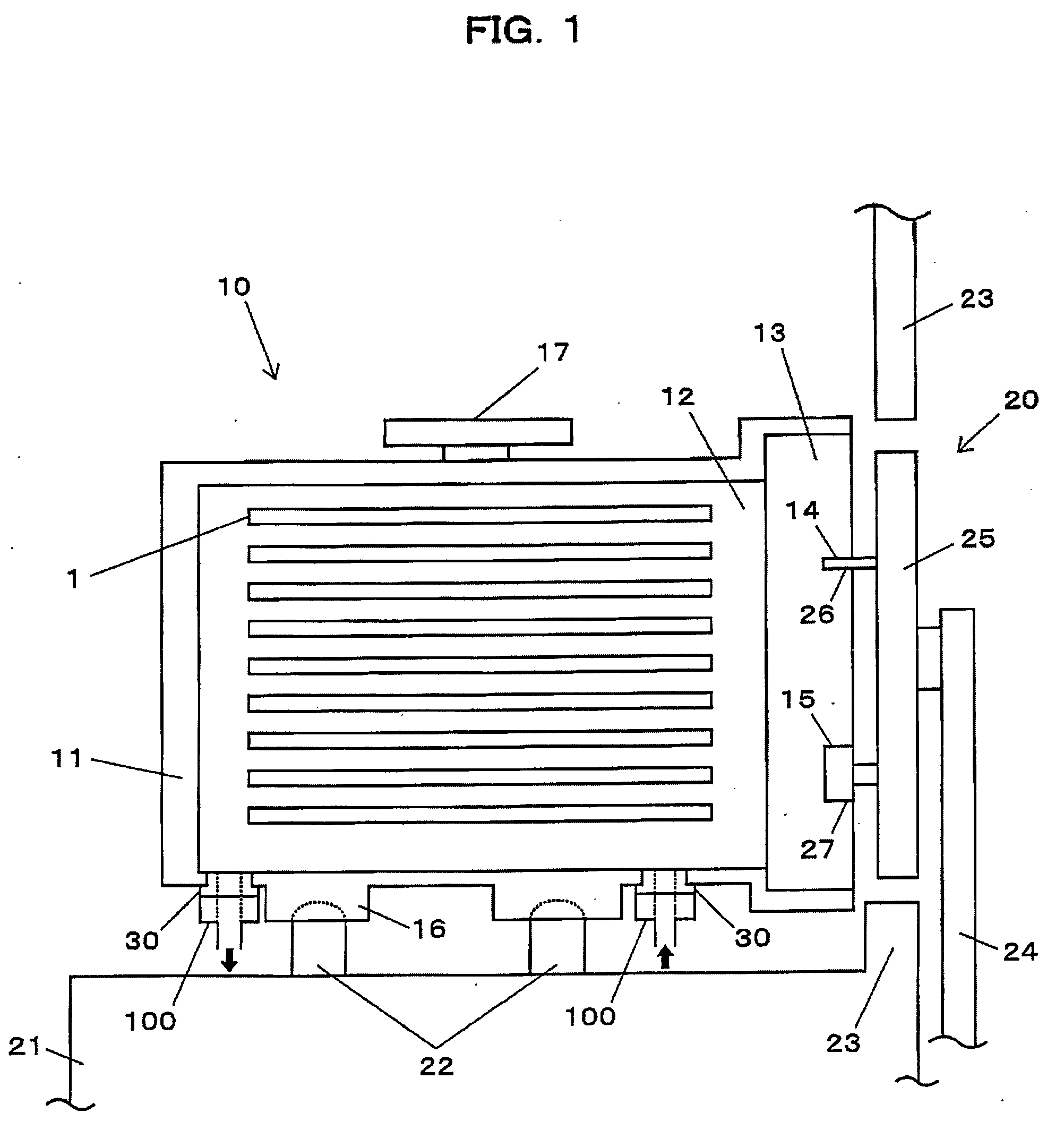
[0044]FIG. 1 is a view showing a state in which a wafer carrier is mounted on a load port in which a connecting device according to the present invention is arranged.

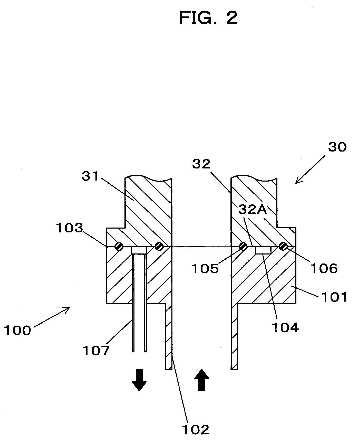
[0045]FIG. 2 is an explanatory view showing the connecting device according to the embodiment 1 of the present invention.

[0046]As shown in FIG. 1, a connecting device 100 is arranged at a position of a purge port 30 of a wafer carrier 10 conveyed by an automatic conveyor, not shown.

[0047]The connecting device 100 is connected to the purge port 30 having a gas inlet 32 into which the purge gas for purging the atmosphere in the wafer carrier 10 flows.

[0048]As shown in FIG. 2, the connection device 100 includes a base 101 formed with a communication port 102, sealing rings 105 and 106 arranged on a surface 103 opposite the purge port 30, a groove 104 formed in the opposite surface 103, etc.

[0049]The connection device 100 includes a pressure-reducing part for reducing the pressure in a space defined by the groove 104 and a ...

embodiment 2

[0053]FIGS. 3A to 3C are explanatory views showing a connecting device 200 according to the present invention. FIG. 3A is a front view of the connecting device 200, FIG. 3B is a view of the connecting device 200 seen from below, and FIG. 3C is a side view of the connecting device 200.

[0054]The connecting device 200 includes a base 201 formed with a communication port 202, a sealing ring 204 arranged on a surface 203 opposite the purge port 30, a holding part 210, a pressing part 220, a cam part 230 for driving the holding part 210 and the pressing part 220, etc. The sealing ring 204 is an O-ring, for example, and is arranged at the peripheral edge of the communication port 202.

[0055]The connecting device 200 includes a mechanism for pressing the base 201 against the purge port 30 by the pressing part 220 with the purge port 30 held by the holding part 210.

[0056]A concrete description will be made hereafter. The cam part 230 is arranged between the holding part 210 and the pressing p...


PUM


Abstract

A connecting device is provided to a wafer carrier for storing a wafer and connected to a purge port having a gas inlet into which a gas for purging an atmosphere in the wafer carrier flows. The connecting device includes, a base; a communication port formed in the base; and a close-contact mechanism that includes, a sealing ring, a groove, and a pressure-reducing passage that communicates with the groove. The pressure in a space defined by the groove and a peripheral edge of the gas inlet is reduced at a position where the base makes contact with the purge port, bringing the gas inlet into close contact with the communication port.

Description

TECHNICAL FIELD[0001]The present invention relates to a connecting device connected to an atmosphere purge port for purging the atmosphere in a wafer storage container (refer hereafter to as wafer carrier) for storing various substrates (refer hereafter to as wafers) such as a silicon wafer by introducing a desired gas (N2 gas or the like) into the wafer carrier.BACKGROUND ART[0002]Conventionally, with the wafer carrier of the type, a carrier door is opened by a load port. Then, a wafer is conveyed into a substrate-processing device having higher cleanliness by the substrate-processing device to undergo required processing.[0003]FIGS. 4A and 4B are schematic diagrams showing wafer carrier. FIG. 4A shows a state in which the wafer carrier is mounted on the load port, and FIG. 4B shows a purge port as will be described later. FOUP (Front Opening Unified Pod) and FOSB (Front Opening Shipping Box) are known as wafer carrier.[0004]A wafer carrier 10 stores therein wafers 1 at predetermin...

Claims


Application Information

Patent Timeline
IPC IPC(8): H01L23/02B65D81/20B65D85/90H01L21/00H01L21/677H01L21/68
CPCH01L21/67017H01L21/67775H01L21/67126
Inventor NAGATA, TATSUHIKOYOSHIMURA, TAKEHIKO
Owner RIGHT MFG
Learn More