Induction Motor Control

a technology of induction motors and control devices, applied in the direction of pump control, control systems, positive displacement liquid engines, etc., can solve the problems of accelerated wear and seizure of moving compression elements, the method of estimating motor strength is not only expensiv

Inactive Publication Date: 2008-10-23
CARRIER CORP
View PDF15 Cites 18 Cited by
  • Summary
  • Abstract
  • Description
  • Claims
  • Application Information

AI Technical Summary

Benefits of technology

[0005]It is a general object of the present invention to control the operation of an AC induction motor in response to the slip exhibited by the AC induction motor in operation.

Problems solved by technology

If the compressor is too highly loaded, the drive motor may draw too much electric current in order to drive the compressor to meet the load demand, resulting in overheating of the motor or overloading other internal compressor components that may damage them or cause a motor protection device to shut the motor down.
If the compressor is too lightly loaded, the drive motor or other internal compressor components may also overheat, particularly under conditions such as low suction pressure, due to too little fluid being pumped through the compressor to adequately cool the drive motor.
Additionally, under the abovementioned conditions, compressor oil may loose its lubrication properties causing accelerated wear and seizure of moving compression elements.
Accordingly, this method of estimating motor strength is not only expensive due to the cost of the required sensors and associated controls, but also carries a relatively substantial level of uncertainty.
Alternate methods of determining the motor loading by measuring various electric parameters, such as the current draw, the voltage level and power factor of the electricity supplied to the motor, or the voltage level and the electric power draw directly, also require a plurality of sensors and are expensive, especially in the case of three-phase motors.

Method used


Image

  • Induction Motor Control
  • Induction Motor Control
  • Induction Motor Control

Examples


Embodiment Construction

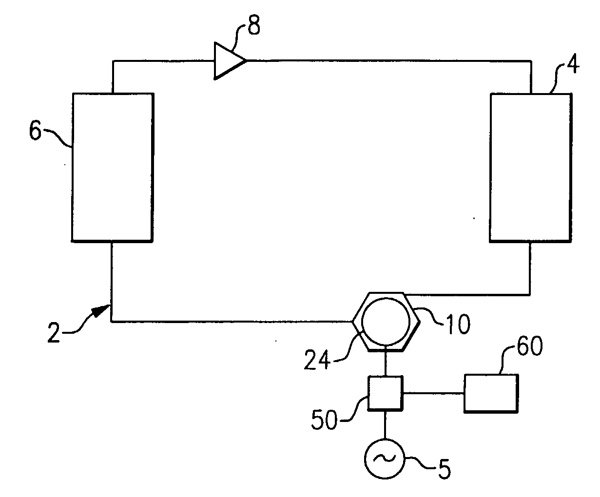
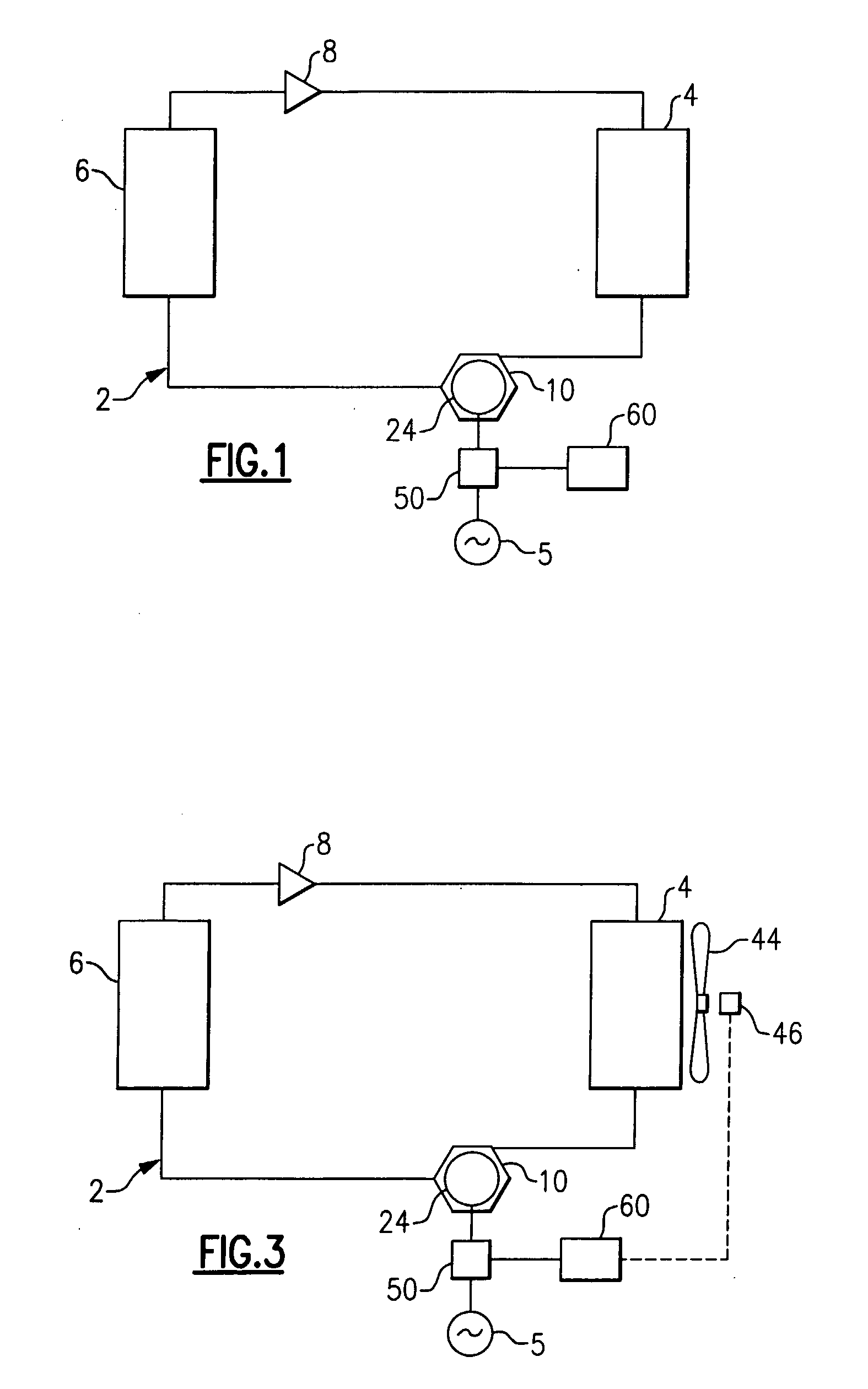
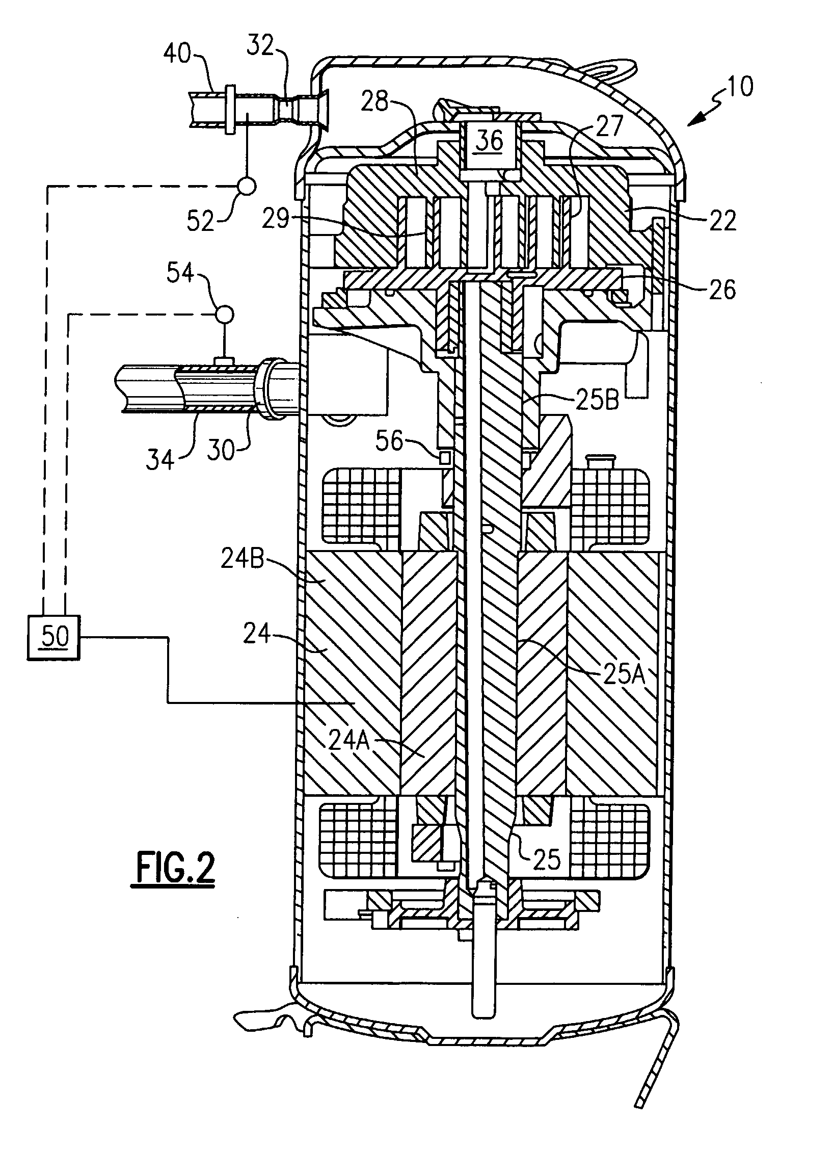
[0021]Referring now to FIG. 1, the present invention will be described herein with respect to a compressor installed in a vapor compression system, such as, for example, an air conditioning or refrigeration circuit. However, it should be understood that the refrigerant circuit is used for illustration of the proposed concept, and that this invention can be applied to any installation where an induction motor drives any other component under load, for example a pump, an appliance or other device. For a refrigerant circuit, such as commonly found in air conditioning or refrigeration systems, having a condenser 4, an evaporator 6, an expansion device 8, and a compressor 10 connected in the conventional manner in refrigerant flow communication by refrigerant lines so as to form the refrigerant circuit 2. The present invention will also be described herein with respect to a scroll compressor. It is to understood, however, that the present invention may be applied to screw compressors, ro...


PUM


Abstract

The operation of an AC induction motor 24 is controlled in response to the actual slip exhibited by the motor during operation. The slip of the motor 24 may be determined by determining the actual running speed, n, of the motor shaft 25A, measuring the line frequency, ns, of the electricity supplied to the motor, and calculating the slip, S, of the motor using the relationship: S=((ns−n)/ns)*100. If the slip is too high when compared to a predetermined maximum acceptable slip, corrective action is taken to decrease the loading on the motor. If the slip is too low when compared to a predetermined minimum acceptable slip, corrective action is taken to increase the loading on the motor. By adjusting the operation of the system by appropriately changing the load on the motor, or changing the electrical supply parameters, the actual slip exhibited by the motor 24 is returned to a value within the range between the minimum acceptable slip and the maximum acceptable slip, thereby protecting the motor and improving overall reliability.

Description

TECHNICAL FIELD[0001]The present invention relates generally to AC induction motors, and more particularly, to a method for controlling the operation of an AC induction motor when driving a load-bearing device, for example a compressor having a shaft driven in rotation by an AC induction motor.BACKGROUND OF THE INVENTION[0002]In many industrial applications, load-bearing devices, for example, pumps, compressors, appliances and the like are driven by an electric motor, typically an AC induction motor. For example, in air conditioning and refrigeration systems, a compressor is provided to compress a refrigerant and pass that refrigerant through a refrigeration circuit and associated system components such as a condenser, an evaporator and an expansion device. The refrigerant, or other fluid, is compressed as it passes through compression elements associated with a compressor shaft driven in rotation by a drive motor. In conventional practice, these drive motors are commonly AC inducti...

Claims


Application Information

Patent Timeline
Patent Type & Authority Applications(United States)
IPC IPC(8): F04B49/06H02P23/08
CPCH02P23/08
Inventor LIFSON, ALEXANDERTARAS, MICHAEL F.
Owner CARRIER CORP
Why Eureka
Try Eureka