Method of calculating approach trajectory for aircraft

a technology of approach trajectory and aircraft, applied in the direction of navigation instruments, instruments, process and machine control, etc., can solve the problems of inability to hold the vertical profile optimized to reduce nuisance, and the large deployment of continuous descent approach procedures

Inactive Publication Date: 2008-10-23
THALES SA
View PDF3 Cites 55 Cited by
  • Summary
  • Abstract
  • Description
  • Claims
  • Application Information

AI Technical Summary

Benefits of technology

[0025]The aim of the device according to the invention is to give the crew the means to decide and negotiate with the controller by calculating for them and by presen

Problems solved by technology

The major problem which today prevents massive deployment of continuous descent approach procedures, stems from the way in which controllers must operate and the current process for constructing the lateral segments for approach procedures.
Specifically, during these phases

Method used


Image

  • Method of calculating approach trajectory for aircraft
  • Method of calculating approach trajectory for aircraft
  • Method of calculating approach trajectory for aircraft

Examples


Embodiment Construction

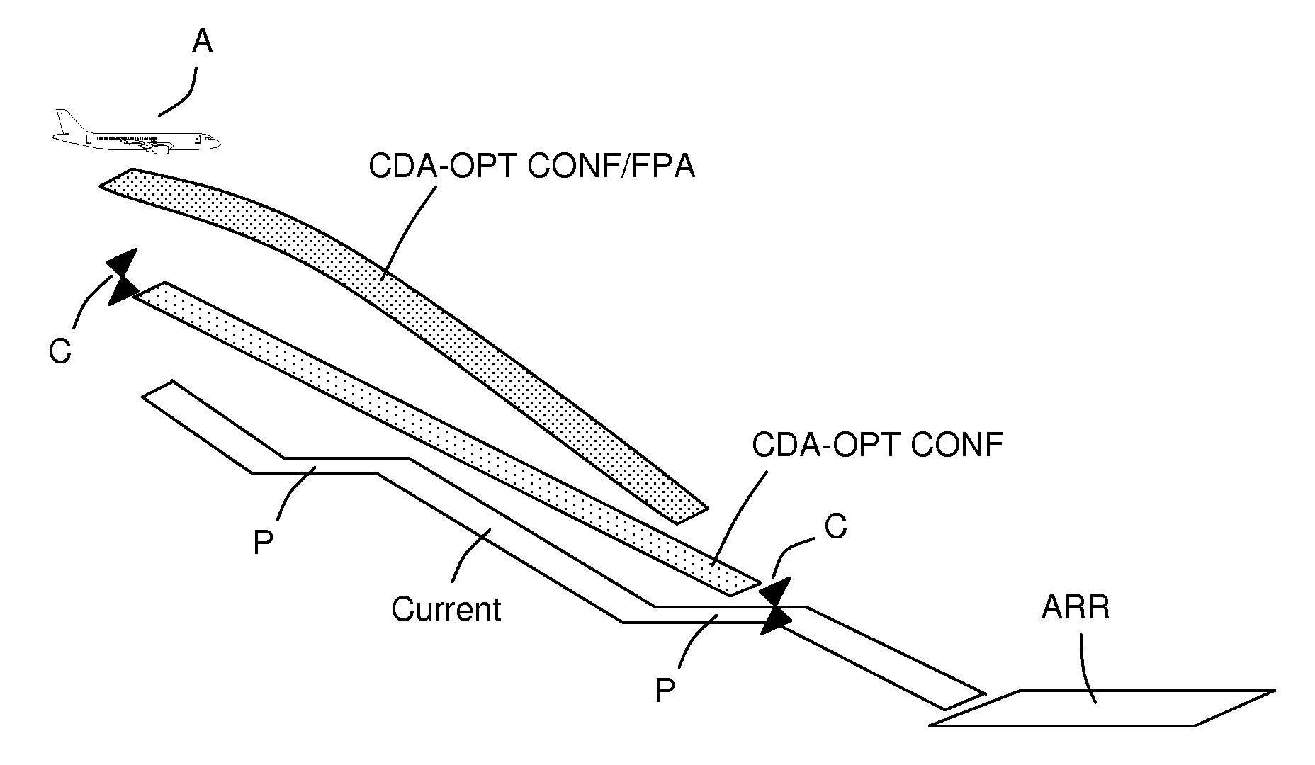
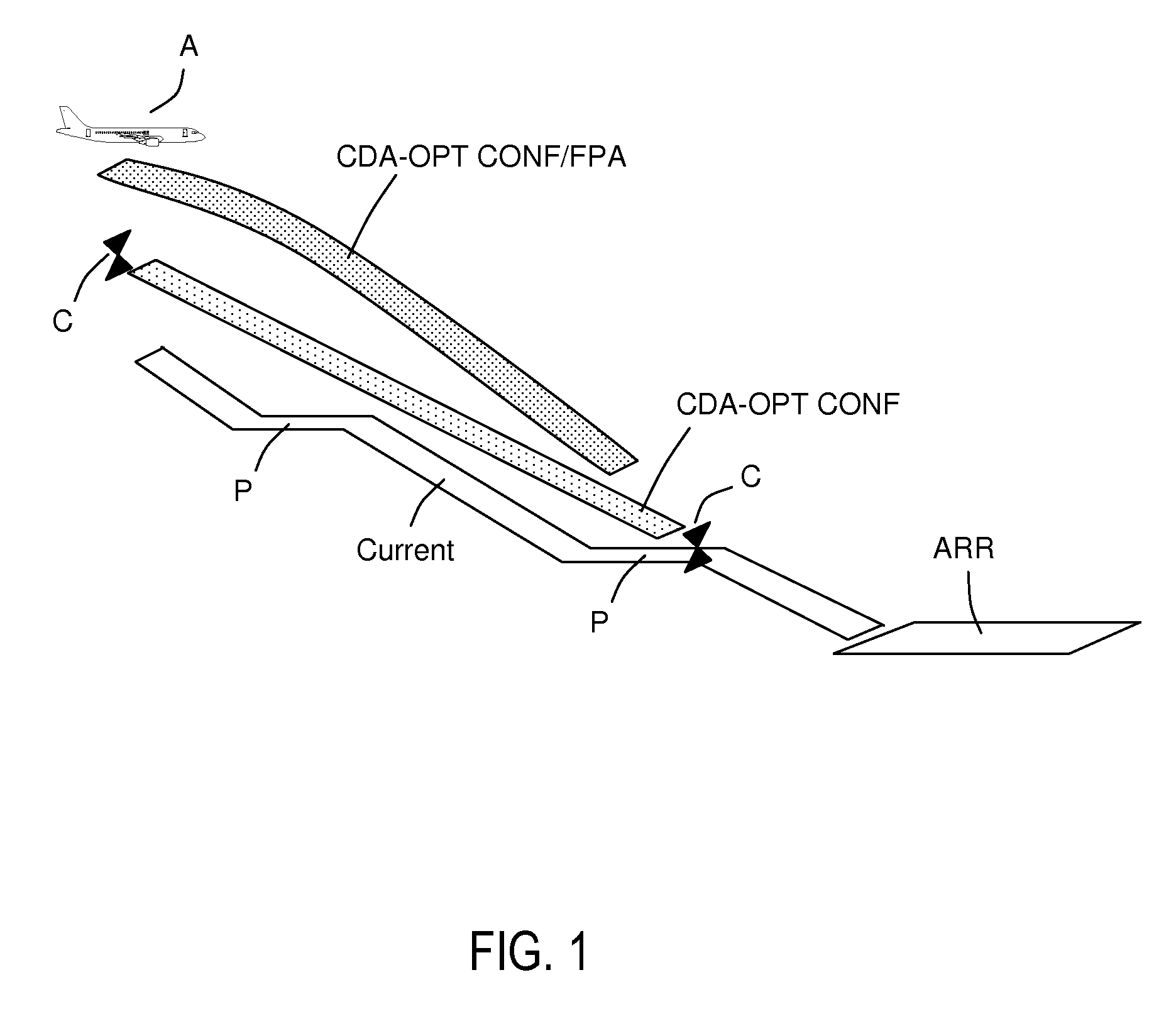
[0046]Each of the points defined arbitrarily by the FMS on semi-infinite legs is dubbed Proj(i). The flight management system according to the invention replaces the visualization of this point by that of the two ends of a segment [Proj(i)_early, Proj(i)_late] such that the points Proj(i)_early and Proj(i)_late correspond respectively to the minimum and maximum distances that the aircraft can travel while preserving its continuous descent approach procedure, so that, if the flight plan unfurls by choosing a point Proj(i) inside this segment, then the continuous descent approach remains possible.

[0047]The steps of the method according to the invention are described below. In a first step, the FMS calculates conventionally the distance corresponding to the lateral flight plan passing through the “conventional” points Proj(i) as was detailed above. This distance is dubbed Dist_reference.

[0048]In a second step, the FMS constructs backwards, starting from the runway, a continuous descent...


PUM


Abstract

The general field of the invention relates to a method of calculating a so-called continuous descent approach procedure for aircraft. The method comprises calculation steps making it possible to determine a minimum distance making it possible to attain the runway by using the highest possible descent angles allowed by the performance of the aircraft, a maximum distance making it possible to attain the runway by using the lowest possible descent angles allowed by the performance of the aircraft, a step of comparing the minimum and maximum distances with a reference distance, the continuous descent approach procedure being possible if this reference distance is less than the maximum distance and greater than the minimum distance. The method also envisages replacing certain indeterminate points of the flight plan by points arising from the minimum and maximum distance calculations.

Description

RELATED APPLICATIONS[0001]The present application is based on, and claims priority from, French Application Number 07 02893, filed Apr. 20, 2007, the disclosure of which is hereby incorporated by reference herein in its entirety.BACKGROUND OF THE INVENTION[0002]1. Field of the Invention[0003]The field of the invention relates to methods of calculating approach trajectories for aircraft. The object of the invention is to optimize an aircraft's approach trajectory to an airport so as to best limit the environmental nuisance above the airport zones. This nuisance is essentially noise and greenhouse gas emissions. Terminal procedures for takeoff or landing have been the subject since the 1990s of research to decrease this nuisance.[0004]2. Description of the Prior Art[0005]FIG. 1 represents various approach profiles for landing an aircraft A on a landing runway ARR. The non-optimized current procedures comprise alternate plateaus and descent segments as indicated in the white staircase ...

Claims


Application Information

Patent Timeline
IPC IPC(8): G01C21/00
CPCG08G5/0039G08G5/025Y02T50/84G05D1/0676Y02T50/80
Inventor COULMEAU, FRANCOISPUTZ, GUILHEM
Owner THALES SA
Why Eureka
Try Eureka