
Road-surface friction-coefficient estimating device

a technology of friction coefficient and estimating device, which is applied in the direction of underwater vessels, special data processing applications, and steering of non-deflectable wheels. it is difficult to perform vehicle behavior control with high accuracy, and the acceleration control amount that corresponds to a low road is unfavorabl

Active Publication Date: 2008-10-23
SUBARU CORP
View PDF8 Cites 47 Cited by
  • Summary
  • Abstract
  • Description
  • Claims
  • Application Information

AI Technical Summary

Benefits of technology

The present invention provides a device for estimating the friction coefficient of a road surface. This device can appropriately set a friction coefficient even in difficult conditions, allowing for better control of vehicle behavior. The device includes a vehicle speed sensor, a vehicle-wheel slip-angle sensor, a restoring-speed setting unit, and a friction-coefficient estimating unit. The device can detect the vehicle speed and the slip angle of the wheel, and will set a restoring speed at which the friction coefficient should be restored to a pre-set value based on these inputs. The device can then estimate the friction coefficient by allowing it to be restored to the set value at the restoring speed. This device can help to improve vehicle behavior control and safety on the road.

Problems solved by technology

However, in the above-mentioned device , there are cases where estimation of a road-surface friction coefficient is not possible such as when a steering angle is at 0°.
This makes it difficult to perform vehicle behavior control with high accuracy.
For example, in the case of traction control where torque is controlled by calculating an optimum grip force using an estimated value of a road-surface friction coefficient, an acceleration control amount that corresponds to a low μ road will be unfavorably set even though the vehicle is actually on a high p road.
In this case, there is a possibility that the vehicle will not exhibit its original acceleration performance.

Method used


Image

  • Road-surface friction-coefficient estimating device
  • Road-surface friction-coefficient estimating device
  • Road-surface friction-coefficient estimating device

Examples


Embodiment Construction

[0017]Embodiments of the present invention will now be described with reference to the drawings.

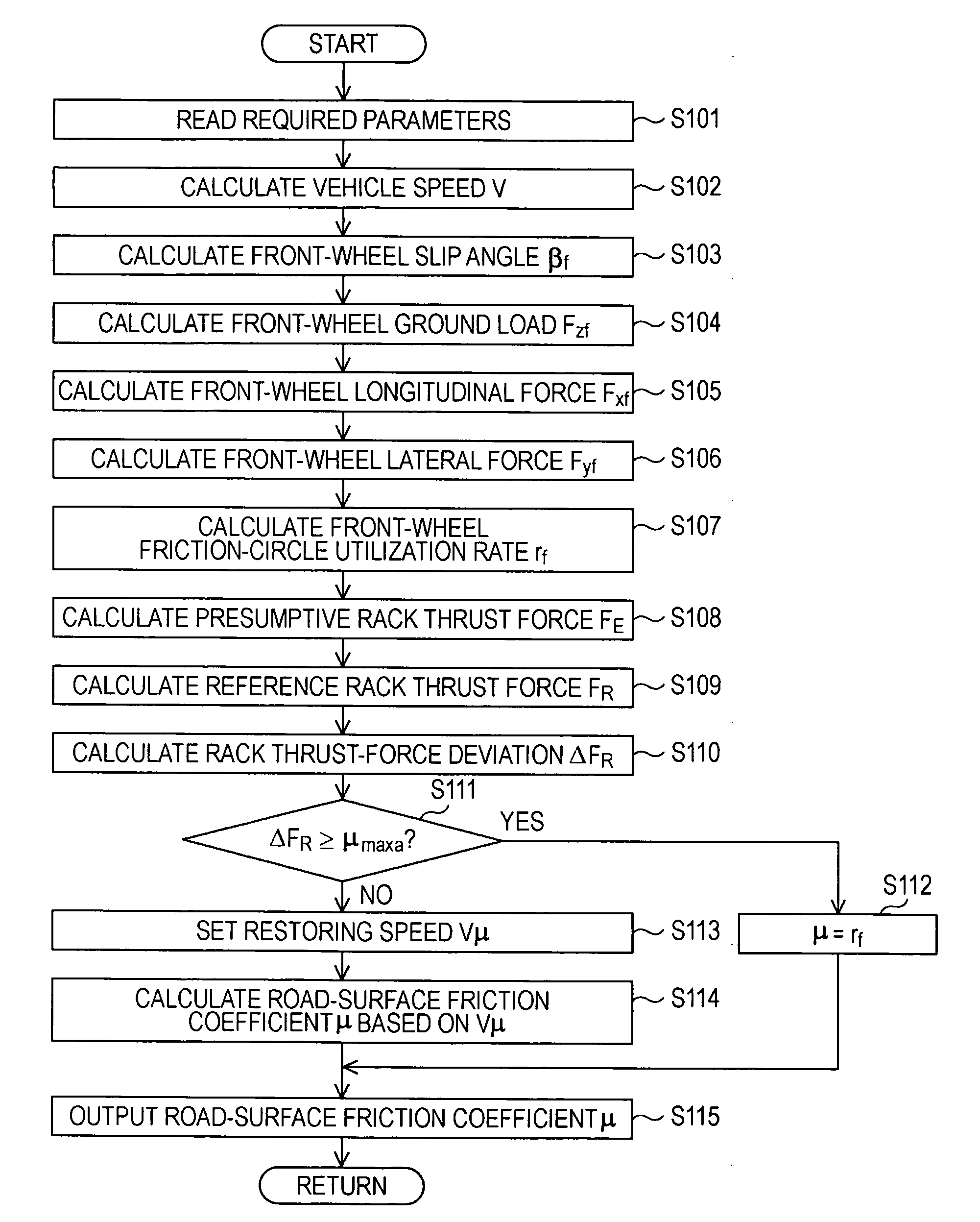
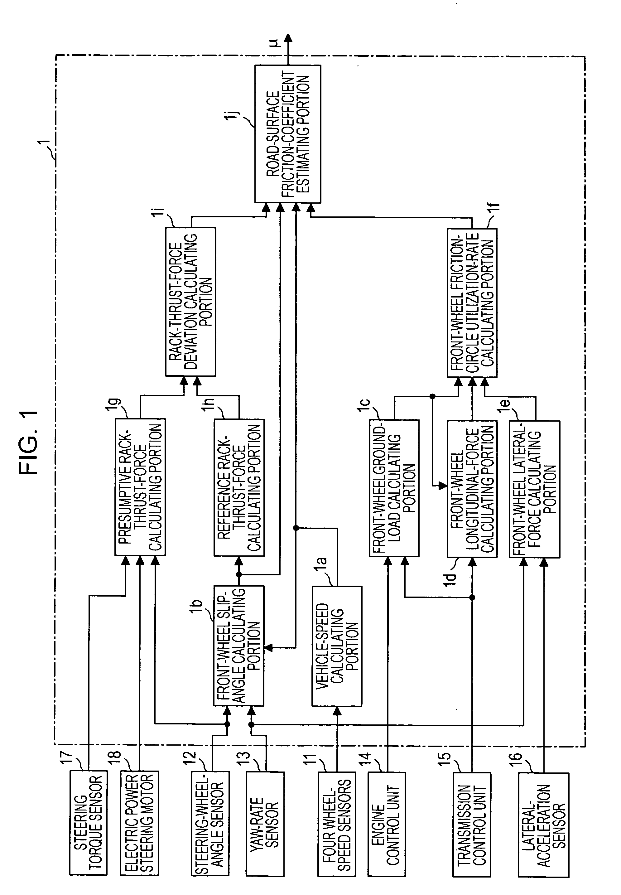
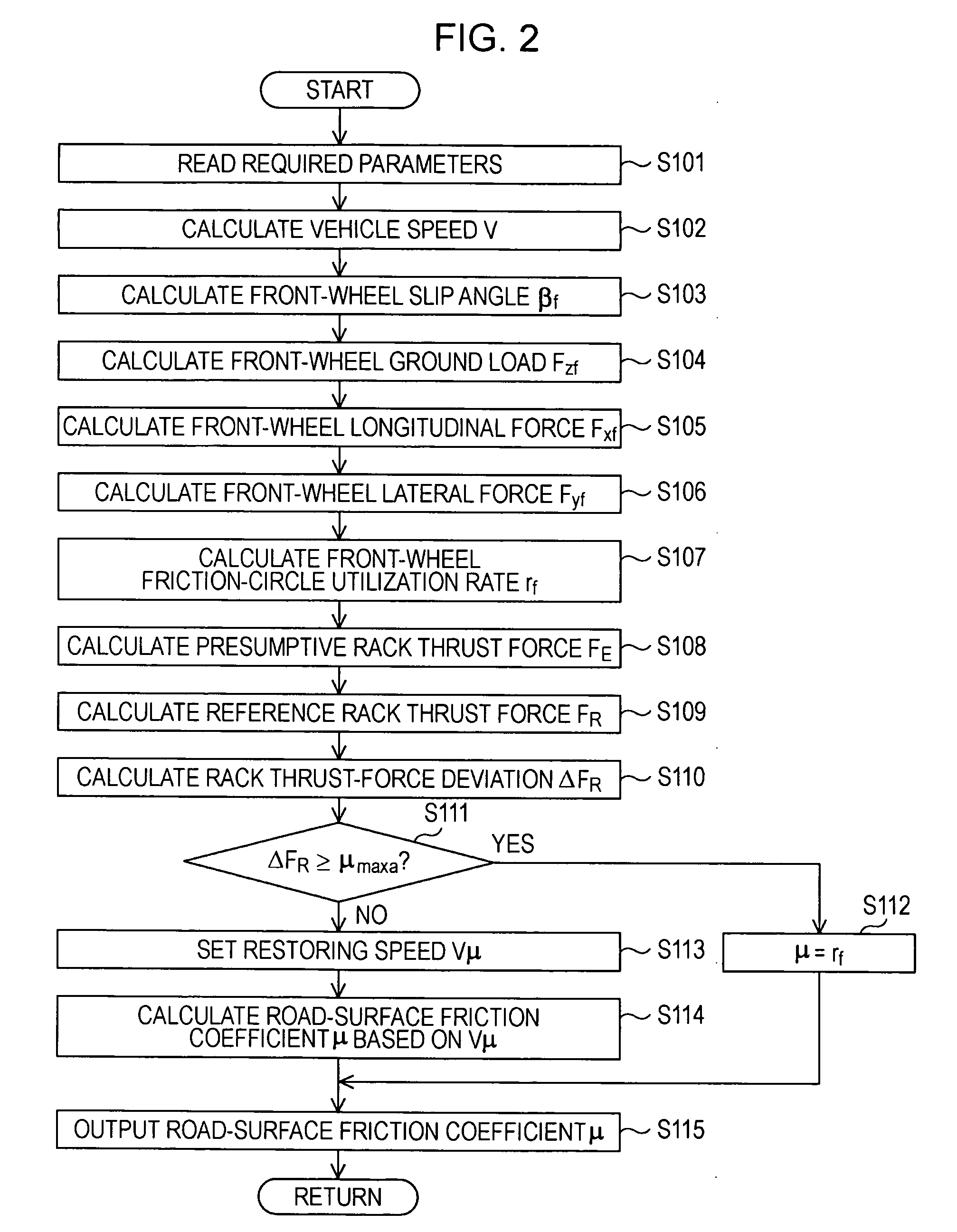
[0018]FIGS. 1 to 6 illustrate an embodiment of the present invention. Specifically, FIG. 1 is a functional block diagram of a road-surface friction-coefficient estimating device, FIG. 2 is a flow chart of a road-surface friction-coefficient estimating program, FIG. 3 is a diagram illustrating steering-angle versus steering-torque characteristics, FIG. 4 is a characteristic diagram of a restoring speed set in accordance with a vehicle speed and a front-wheel slip angle, FIG. 5A illustrates a relationship between a steering-stability capacity and a vehicle speed, FIG. 5B illustrates a relationship between a steering-stability capacity and a slip angle, and FIG. 6 is a timing diagram that shows an example of road-surface friction-coefficient estimation according to this embodiment. In this embodiment, a vehicle equipped with the road-surface friction-coefficient estimating device is directed...


PUM


Abstract

A road-surface friction-coefficient estimating device compares a rack-thrust-force deviation value with a preliminarily set maximum-value-determination threshold value. If the rack-thrust-force deviation value is above the maximum-value-determination threshold value, the device determines that tires are slipping, and sets a front-wheel friction-circle utilization rate in that state as a road-surface friction coefficient. If the rack-thrust-force deviation value is below the maximum-value-determination threshold value, the device refers to a preliminarily set map to determine a restoring speed at which the road-surface friction coefficient is to be restored to 1.0 based on a vehicle speed and a front-wheel slip angle. While restoring the road-surface friction coefficient at the restoring speed, the device calculates and outputs the road-surface friction coefficient.

Description

CROSS REFERENCES TO RELATED APPLICATIONS[0001]The disclosure of Japanese Patent Application No. 2007-109622 filed on Apr. 18, 2007 including the specifications, drawings, and abstracts are incorporated by references herein.BACKGROUND OF THE INVENTION[0002]1. Field of the Invention[0003]The present invention relates to a road-surface friction-coefficient estimating device of a vehicle estimating a road-surface friction coefficient over a broad driving range.[0004]2. Description of the Related Art[0005]In recent years, there have been developed and put in practical use various control technologies for vehicles, such as traction control, braking-force control, and torque-distribution control. These technologies generally utilize a road-surface friction coefficient for the calculation or correction of required control parameters. In order to perform the control properly, it is necessary to estimate a road-surface friction coefficient with high accuracy.[0006]With regard to technologies ...

Claims


Application Information

Patent Timeline
Patent Type & Authority Applications(United States)
IPC IPC(8): G06F7/00B60W40/068B62D6/00B62D101/00B62D111/00B62D113/00B62D119/00B62D137/00
CPCB60W40/068B60W2510/202
Inventor KOGURE, MASARUMATSUNO, KOJIYONEDA, TAKESHI
Owner SUBARU CORP
Learn More