Method and apparatus for attenuating fuel pump noise in a direct injection internal combustion chamber

a technology of internal combustion chamber and fuel pump, which is applied in the direction of mechanical equipment, liquid fuel feeders, machines/engines, etc., can solve the problems of vibration and possible part fatigue, audible and undesirable noise, and fuel pressure pulsations to the fuel rail, so as to dampen the fuel pressure fluctuations and dampen the fuel pressure pulsations

Active Publication Date: 2008-10-30
HITACHI LTD
View PDF16 Cites 18 Cited by
  • Summary
  • Abstract
  • Description
  • Claims
  • Application Information

AI Technical Summary

Benefits of technology

[0013]In a modification of the invention, the fuel injector is mounted to the injector cup so that the fuel injector may pivot or swivel slightly relative to the injector cup. Tapered surfaces on the injector reduce the bending arm between the injector and its mounting clip and thus reduces stress.
[0015]Consequently, during operation of the fuel rail, the high pressure within the fuel rail simultaneously imposes a force on both O-rings that are substantially equal in magnitude, but opposite in direction. As such, fuel pressure on the fuel injector in a direction towards the injector tip that would otherwise occur, together with vibrations resulting from that axial force, is avoided.
[0017]In another form of the invention, the reservoir is positioned between the fuel rails and each of the fuel injectors. Such fuel reservoirs also serve to dampen the fuel pressure pulsations from the fuel pump.
[0018]In yet another form of the invention, a small diameter orifice is provided between the fuel rail and each fuel injector. These small diameter orifices also act to dampen the fuel pressure fluctuations, and thus transmission of vibration from the fuel pump and to the fuel injectors.

Problems solved by technology

One disadvantage of these previously known direct fuel injection engines, however, is that the fuel pump is typically cam driven and thus creates fuel pressure pulsations to the fuel rail.
These fuel pump pulsations disadvantageously result in vibrations that are transmitted by the fuel injectors to the engine block and create an audible and undesirable noise as well as vibration and possible part fatigue.

Method used


Image

  • Method and apparatus for attenuating fuel pump noise in a direct injection internal combustion chamber
  • Method and apparatus for attenuating fuel pump noise in a direct injection internal combustion chamber
  • Method and apparatus for attenuating fuel pump noise in a direct injection internal combustion chamber

Examples


Embodiment Construction

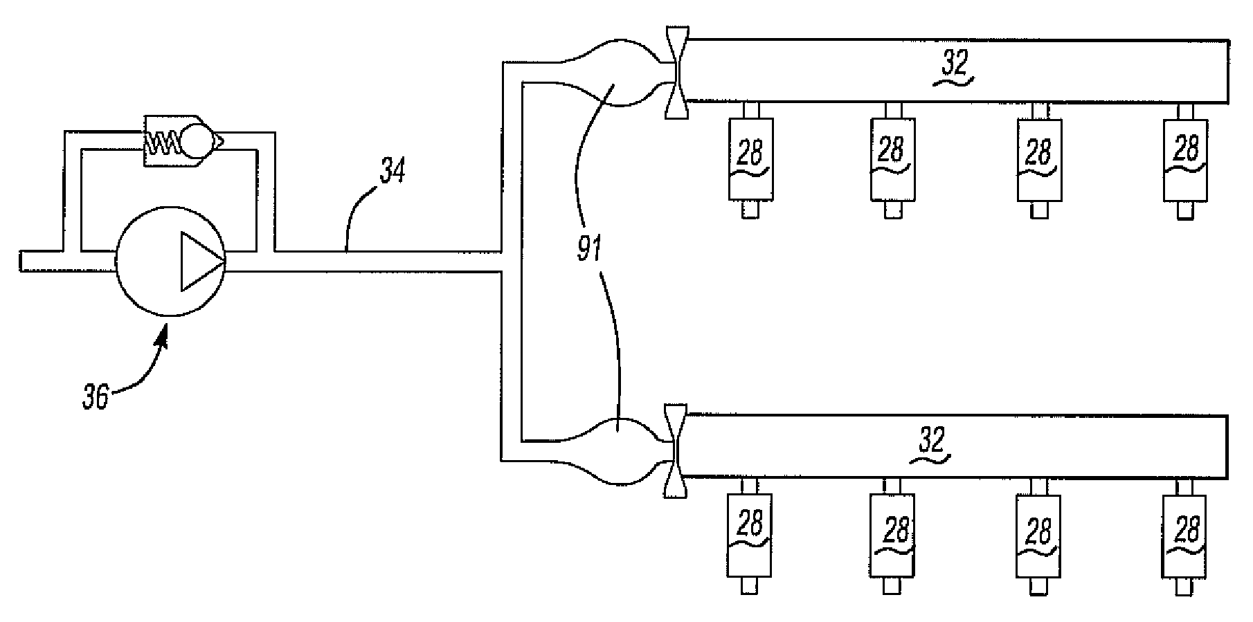
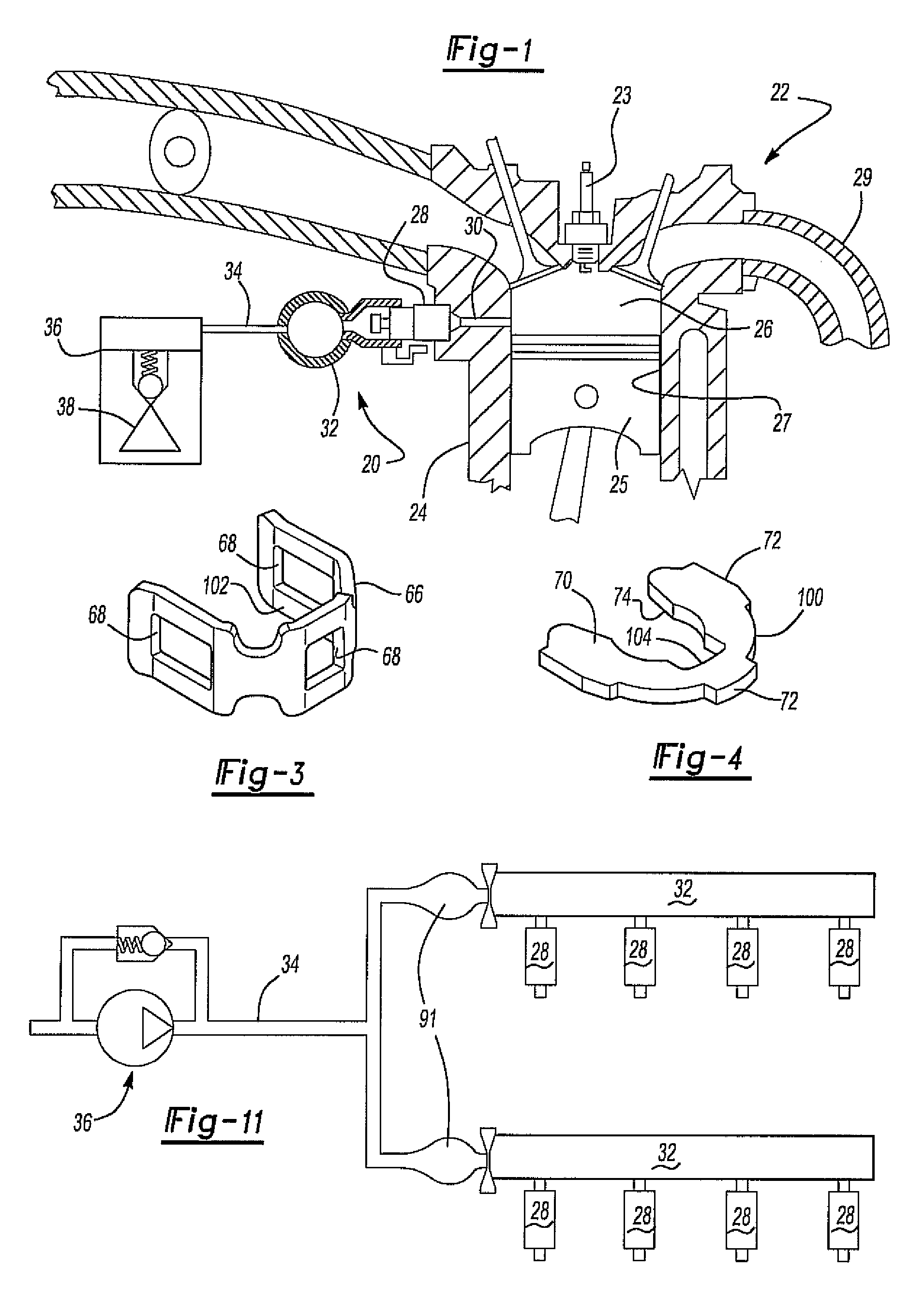
[0034]With reference first to FIG. 1, a fuel delivery system having a direct injection nozzle assembly 20 in accordance with one form of the present invention is illustrated for use with a direct injection internal combustion engine 22. The engine 22 includes an engine block 24, including the cylinder head, which defines at least one, and more typically several, internal combustion chambers 26.

[0035]A spark plug 23 initiates the fuel combustion in the combustion chamber 26 to drive a piston 25 reciprocally mounted in a cylinder 27 in the engine block 24. Following fuel combustion, the combustion products are exhausted through an exhaust manifold 29.

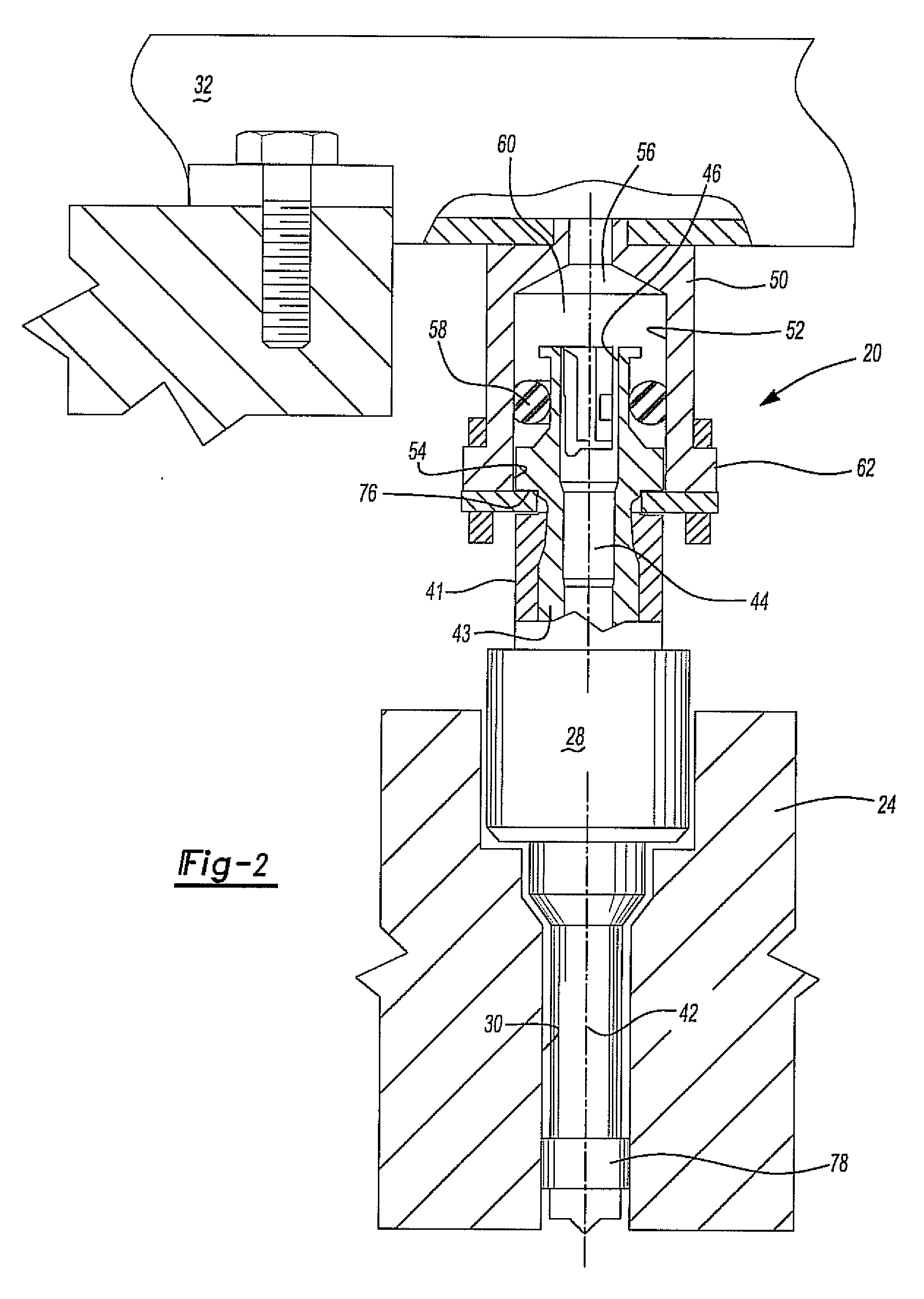
[0036]A direct injection fuel injector 28 is associated with each combustion chamber 26. Each fuel injector 28, furthermore, includes a portion mounted within a passageway 30 formed in the engine block 24 and open to the combustion chamber 26. One fuel injector 28 is associated with each combustion chamber 26.

[0037]The fuel injector 28, w...


PUM


Abstract

An apparatus for attenuating fuel pump noise in a direct injection internal combustion engine. In one proposal, the direct injection fuel nozzle is suspended from a fuel rail in a fashion that avoids direct metal-to-metal contact between the injector and the engine block. The direct injection nozzle may also be connected to the fuel rail by a pair of spaced-apart seals which equalize the longitudinal pressure on the nozzle during operation. Enlarged diameter fuel reservoirs and / or a restricted orifice may be provided fluidly in series between the fuel pump and the direct injection nozzle in order to attenuate noise resulting from fuel pump pulsation. A clip holder and clip plate mount the fuel injector to the injector cup.

Description

CROSS REFERENCE TO RELATED APPLICATIONS[0001]This application is a continuation-in-part of U.S. patent application Ser. No. 11 / 695,195 filed Apr. 2, 2007.BACKGROUND OF THE INVENTION[0002]I. FIELD OF THE INVENTION[0003]The present invention relates to a method and apparatus for attenuating noise resulting from fuel pump pulsation in a direct injection internal combustion engine.[0004]II. DESCRIPTION OF RELATED ART[0005]Direct injection internal combustion engines have enjoyed increased acceptance for a variety of reasons. In particular, direct fuel injection into the engine combustion chamber typically results in better fuel economy and more efficient operation of the internal combustion engine.[0006]In a direct injection internal combustion engine, a passageway is formed in the engine block, which includes the engine cylinder head, that is open to each combustion chamber. A direct injection fuel injector is then positioned within this passageway for each of the engine combustion cha...

Claims


Application Information

Patent Timeline
Patent Type & Authority Applications(United States)
IPC IPC(8): F02M69/46
CPCF02M55/02F02M61/168F02M2200/315F02M2200/40F02M2200/8023
Inventor WATANABE, ATSUSHIHOHKITA, ATSUSHISOMA, MASAHIROSAEKI, HIROAKI
Owner HITACHI LTD
Why Eureka
Try Eureka