Method and system for tracking and positioning continuous cast slabs

a technology of continuous cast and tracking system, applied in the direction of manufacturing tools, mould control devices,foundry moulding apparatus, etc., can solve the problems of strands that may tend to wander, distort, twist, etc., and achieve the effect of reducing the thickness of strands

Active Publication Date: 2008-10-30
NUCOR CORP
View PDF7 Cites 26 Cited by
  • Summary
  • Abstract
  • Description
  • Claims
  • Application Information

AI Technical Summary

Benefits of technology

[0003]The width of the steel strand exiting the mold is determined substantially by the relative separation and taper angle of opposing faces of the casting mold. The molten steel tends to shrink in the mold (i.e., pull away from the mold faces) as it cools and moves from the top of the mold (e.g., adjacent the SEN) to the bottom of the mold. The mold faces are tapered to account for the shrinkage, so that the molten steel moving through the mold may maintain contact with the mold faces.
[0004]As the strand exits downwardly from the casting mold, the strand enters containment segments which serve to further cool and solidify the strand. The rolls of containment segments may also apply pressure to the strand to reduce the thickness of the strand. As the strand exits the containment segments, the strand may enter a set of pinch rolls which serve to feed the hot metal strand downward from the mold and toward a withdrawal straightener. A disconnect roll positioned below the set of pinch rolls may be provided to initially direct the cast metal strand toward the withdrawal straightener and to disconnect a starter dummy bar from the cast metal strand. The dummy bar allows the start of casting by providing a surface onto which to cast the strand at the start of the cast.

Problems solved by technology

As the cast metal strand travels from the casting mold through the casting machine and beyond to the cutting tool, the strand may tend to wander, distort, and twist due to forces exerted on the strand.

Method used


Image

  • Method and system for tracking and positioning continuous cast slabs
  • Method and system for tracking and positioning continuous cast slabs
  • Method and system for tracking and positioning continuous cast slabs

Examples


Embodiment Construction

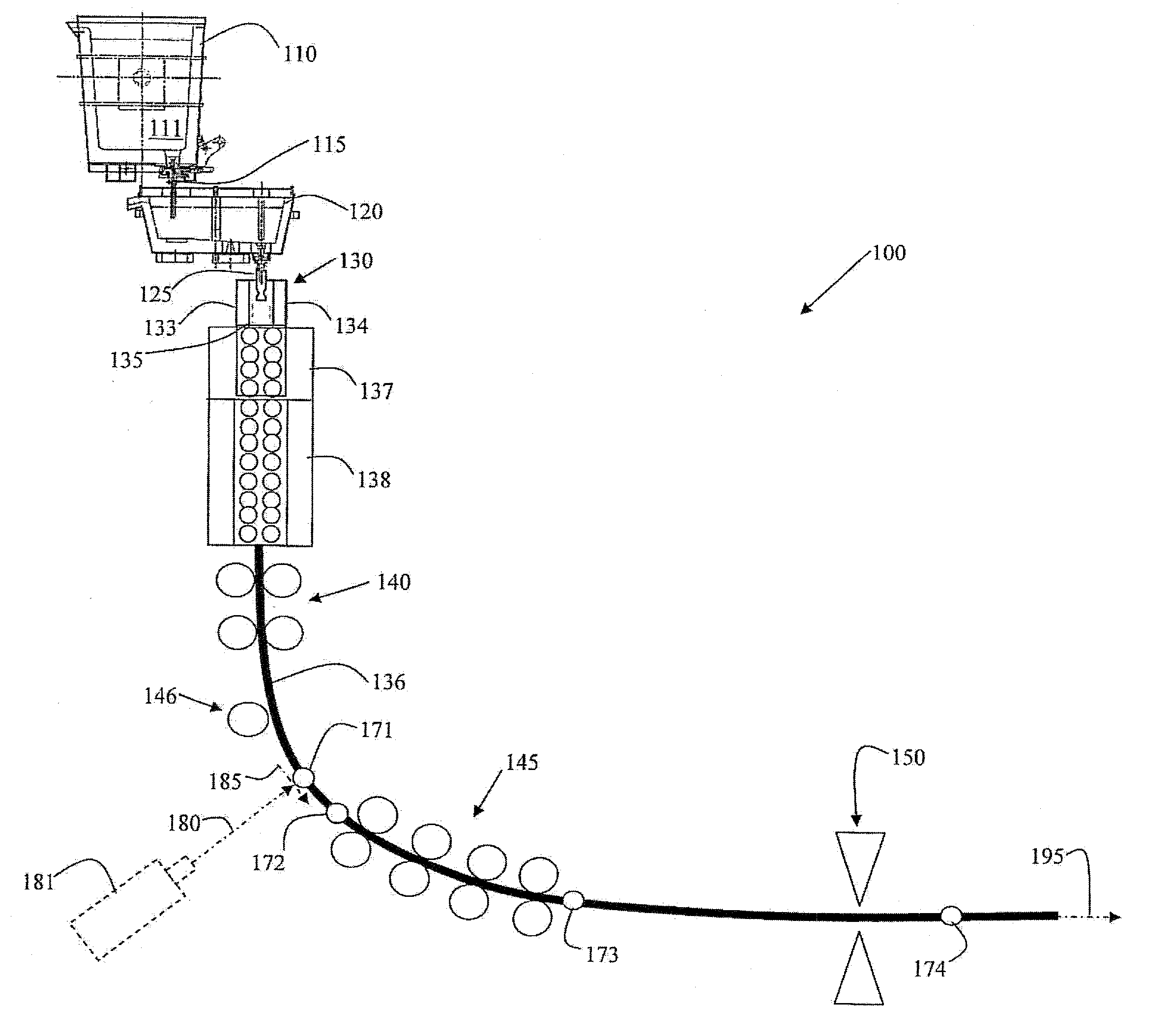
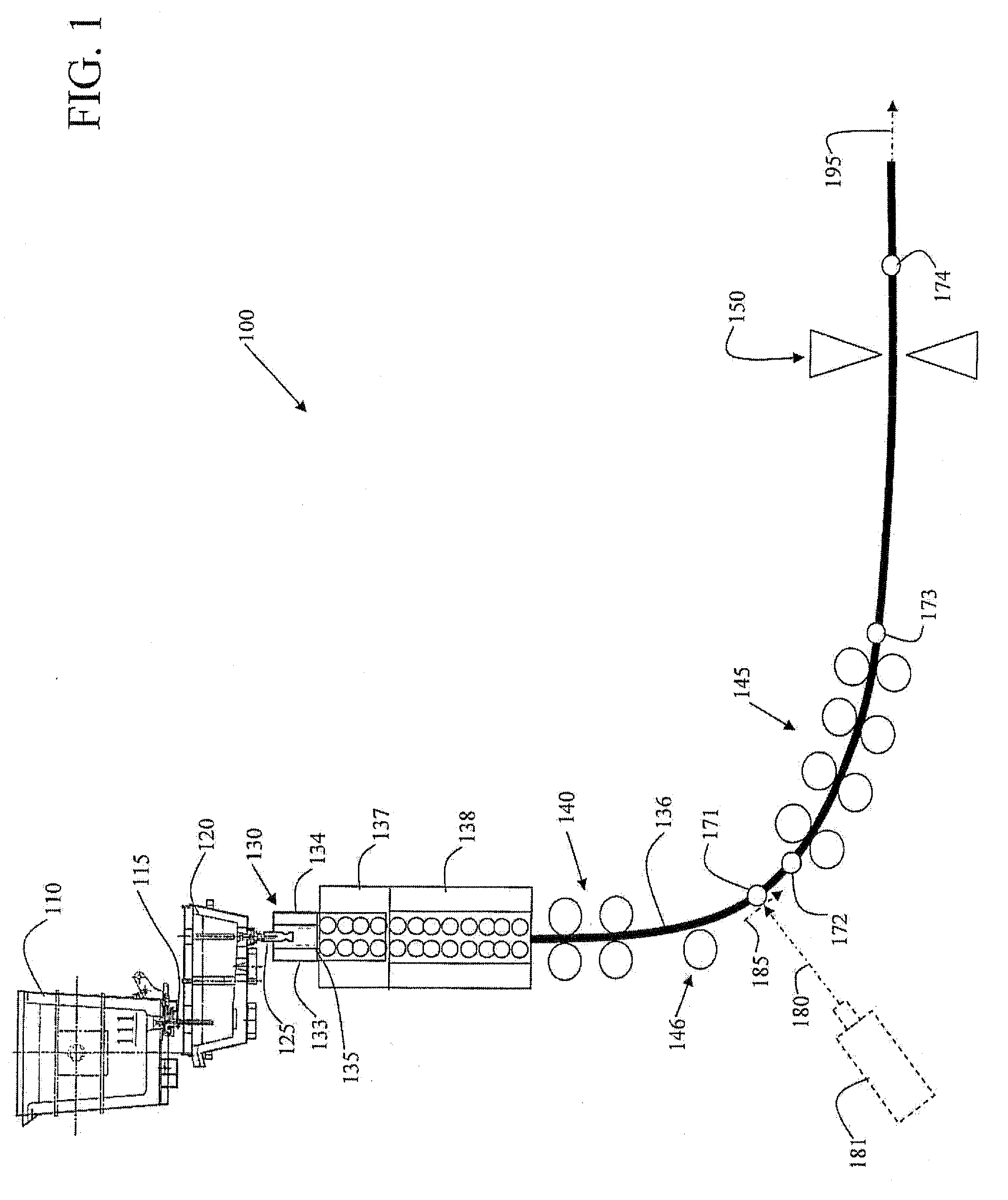
[0057]FIG. 1 is a schematic illustration of an embodiment of a continuous metal slab casting plant 100. The steel slab casting plant 100 includes a ladle 110 to provide molten steel 111 to a tundish 120 through a shroud 115. The tundish 120 directs the molten melt 111 to the casting mold 130 through a submerged entry nozzle (SEN) 125 connected to a bottom of the tundish 120. The casting mold 130 includes at least two opposing mold faces 133 and 134, which may be fixed or moveable. The SEN 125 delivers the molten melt into the casting mold 130 below the surface (“meniscus”) of the molten metal in the casting mold 130.

[0058]The width of the cast strand 136 leaving the casting mold 130 is substantially determined by the configuration of the caster mold faces at the mold exit at 135. The casting mold 130 has two opposing broad mold faces 133 and 134 and two opposing narrow mold faces (not shown) to form a substantially rectangular configuration, or some other desired configuration for t...


PUM

PropertyMeasurementUnit
elevationaaaaaaaaaa
drive speedaaaaaaaaaa
roll forceaaaaaaaaaa

Abstract

A system and method for tracking and positioning a continuous cast strand in a casting plant. Lateral positions and, optionally, elevational positions of a cast strand are monitored by sensors as casting proceeds and are fed to a computer-based system as corresponding position information where the information is stored as associated data. The computer-based system processes the associated data and generates corresponding control signals which are used to control at least one correcting device to maintain desired orientation of the cast strand as casting proceeds.

Description

BACKGROUND AND SUMMARY[0001]Continuous slab casting is a steel making process where molten (liquid) steel from a ladle is continuously cast into cast metal strand of a semi-finished shape (e.g., slabs, blooms, and billets). In a continuous slab caster, the molten metal is fed by gravity from the ladle through a tundish to a subentry nozzle (SEN) in a casting mold. The semi-finished shape is determined by the casting mold which receives the molten steel through the SEN. The steel is cast in the casting mold, which is water cooled, with a solidified outer shell and molten inner core as the strand moves downwardly through the mold which oscillates. The cast metal strand is withdrawn downwardly from the casting mold and is curved by casting guide rollers and straighteners to exit the casting machine laterally in a horizontal direction of travel. The strand is further subjected to secondary cooling upon exiting from the casting machine by direct and / or secondary cooling to solidified the...

Claims


Application Information

Patent Timeline
Patent Type & Authority Applications(United States)
IPC IPC(8): B22D11/16B22D11/14B22D2/00
CPCB22D2/00B22D11/168B22D11/225
Inventor MORALES, DARRELLEVANS, KEVIN
Owner NUCOR CORP
Why Eureka
Try Eureka