Discharge device

Active Publication Date: 2008-10-30
APTAR RADOLFZELL
View PDF17 Cites 9 Cited by
  • Summary
  • Abstract
  • Description
  • Claims
  • Application Information

AI Technical Summary

Benefits of technology

[0010]It is preferred that the air outlet is provided in the region of the feed path, in particular in a region which is at the top in a use position of the discharge device or of the discharge head. The arrangement of the air outlet in the feed path, in particular in an upper region of the feed path, ensures that, when the discharge device is put into operation, the air outlet is not prematurely locked by liquid in the feed path. The remaining air can therefore be discharged through the air outlet even if a substantial part of the feed path is already filled with medium. The air outlet is preferably provided, with reference to a normal use position of the device, approximately level with the disch

Problems solved by technology

A problem technically with discharge devices and discharge heads of this type is that, in the delivery state of the discharge device and after a prolonged period in which the discharge device is not used, the feed path is filled with air.
When the discharge device is put into operation by being actuated, although said air in the feed path is compressed such that the pressure in the feed path or feed path increases,

Method used


Image

  • Discharge device
  • Discharge device
  • Discharge device

Examples


Embodiment Construction

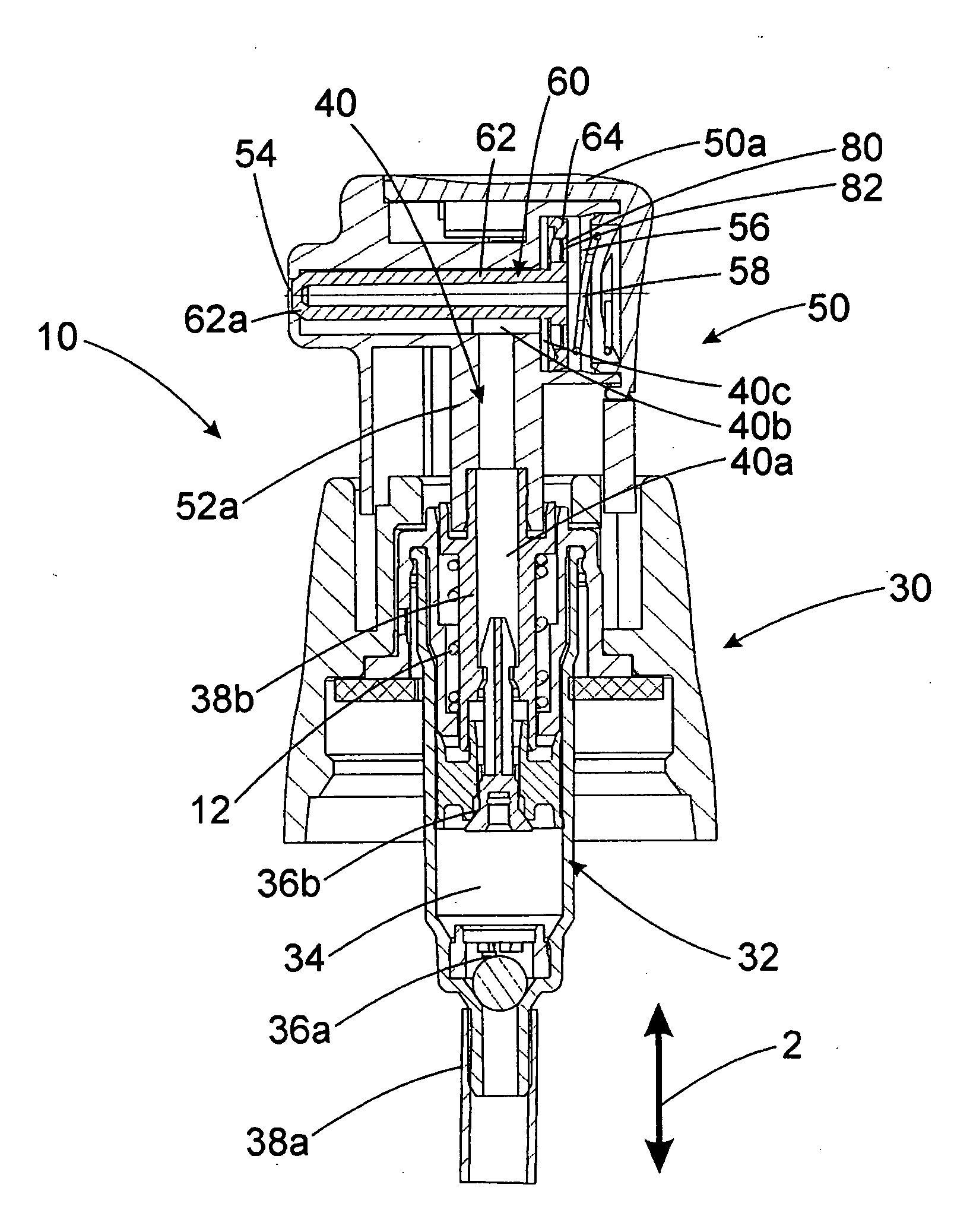
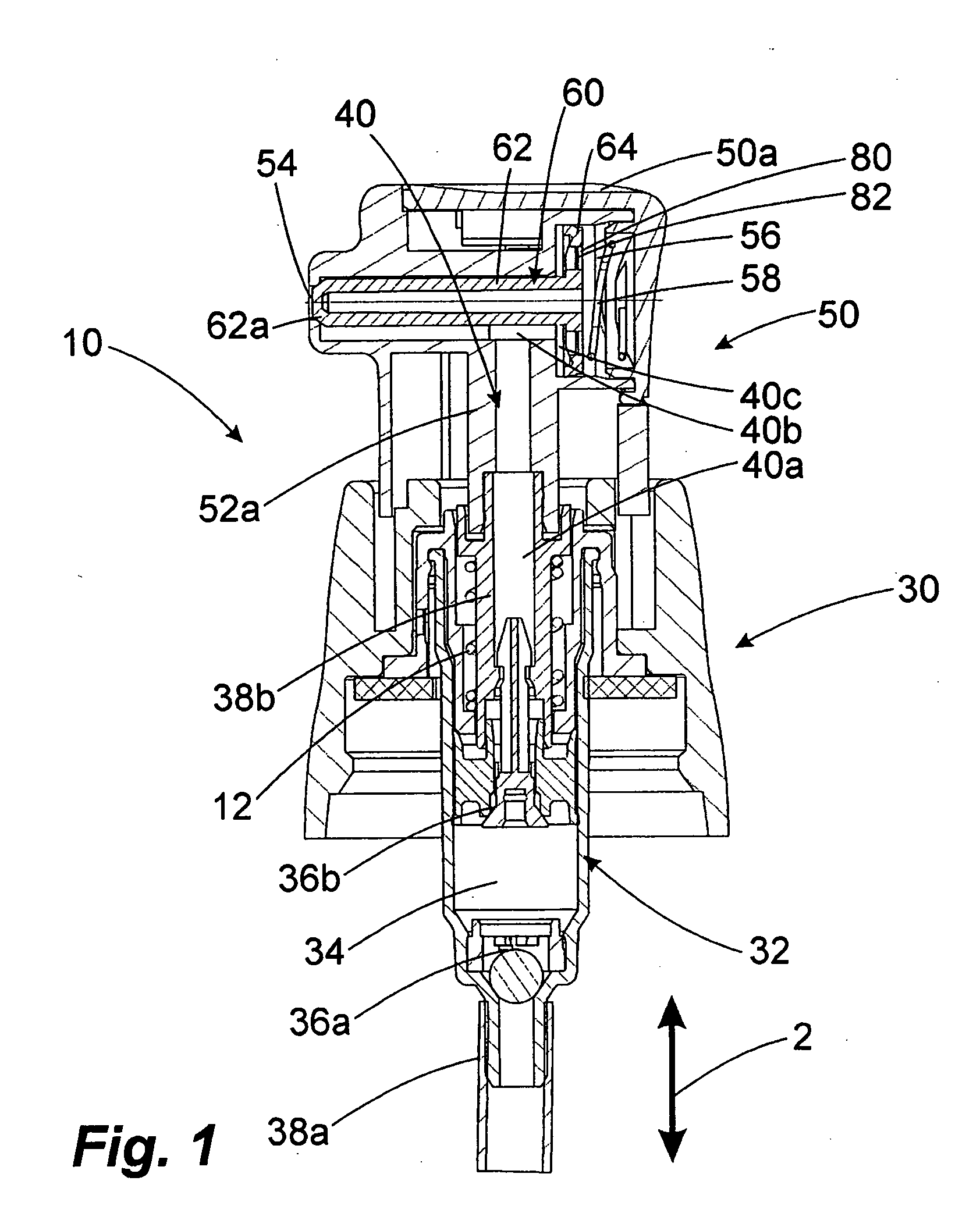
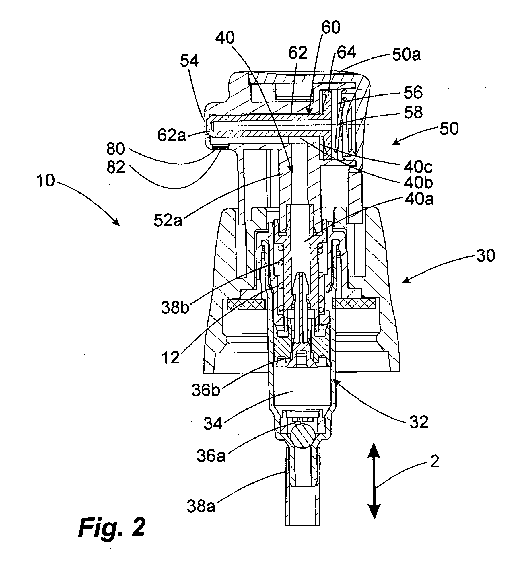
[0021]FIG. 1 shows a discharge device 10 with a pump top part 30 and a discharge head 50. The discharge device 10 is provided for fastening to a media store (not illustrated). The pump top part 30 comprises a pump 32. Said pump 32 has a pump chamber 34 which is closed on the input side by an input valve 36a and on the output side by an output valve 36b. A suction tube 38a through which medium can be conveyed from the media store into the pump chamber 34 is provided on the far side of the input valve 36a.

[0022]The output valve 36b is adjoined by a tube section 38b which defines a first section 40a of a feed path 40. A tube section 52a which is on the discharge head side and delimits part of an approximately L-shaped second section 40b of the feed path 40 is pressed on to the tube section 38b. Said second section 40b of the feed path 40 is adjoined by a pressure chamber 40c and a discharge opening 54.

[0023]The tube section 52a is part of the discharge head 50. By means of the connect...


PUM


Abstract

Discharge device and discharge head.
The invention relates to a discharge device (10) for discharging liquid medium, with a pump device (32) with a variable volume pump chamber (34), a discharge opening (54) for the liquid medium, a feed path (40) between the pump device (32) and the discharge opening (54), and an outlet valve (54, 62a) which is designed to open the discharge opening (54) as a function of the pressure in the feed path (40), and to a discharge head provided for this purpose.
According to the invention, the discharge device or the discharge head has a gas-permeable and liquid-tight air outlet (80) which connects the pump chamber (34) or the feed path (40) to an external environment.
For use at a required high limit pressure of the outlet valve.

Description

FIELD OF APPLICATION AND PRIOR ART [0001]The invention relates to a discharge device for discharging liquid or pasty medium, with a pump device with a variable volume pump chamber, with a discharge opening for the liquid medium, with a feed path between the pump device and the discharge opening, and with an outlet valve which is designed to open the discharge opening as a function of the pressure in the feed path.[0002]The invention furthermore relates to a discharge head for a discharge device, with a discharge opening for discharging liquid medium, a feed path for transporting the medium to the discharge opening, and an outlet valve which is designed to open the discharge opening as a function of the pressure in the feed path.[0003]Generic discharge devices and discharge heads for discharge devices are known from the prior art. When appropriate discharge devices are used, a pump device with a variable volume pump chamber or a pump device of a different kind places medium into the ...

Claims


Application Information

Patent Timeline
IPC IPC(8): B65D88/54B67D5/40B67D7/58
CPCB05B11/0016B05B11/0067B05B11/3023B05B11/3061B05B11/3074B05B11/0044B05B11/1023B05B11/1061B05B11/1074
Inventor BRUDER, THOMASHERZ, ANDIKRAMPEN, GERALD
Owner APTAR RADOLFZELL
Why Eureka
Try Eureka