
Unsplit Bipolar Pulse Forming Line

a transmission line and bipolar technology, applied in pulse train generators, pulse techniques, waveguides, etc., can solve the problems of nonlinearity, heavy, bulky, and difficult to form a single structure, and achieve the effect of avoiding the formation of a single structur

Inactive Publication Date: 2008-10-30
LAWRENCE LIVERMORE NAT SECURITY LLC
View PDF9 Cites 8 Cited by
  • Summary
  • Abstract
  • Description
  • Claims
  • Application Information

AI Technical Summary

Benefits of technology

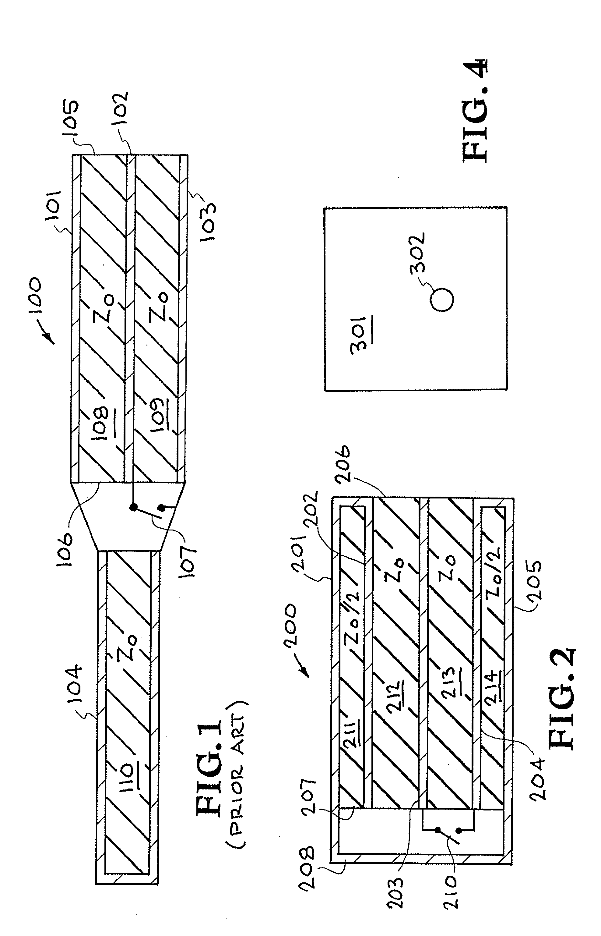
[0009]One aspect of the present invention includes a bipolar pulse forming transmission line module comprising: first, second, third, and fourth conductors sequentially arranged to form an interleaved stack having first and second ends of a transmission line, with a first dielectric layer provided between the first and second conductors, a second dielectric layer provided between the second and third conductors, and a third dielectric layer provided between the third and fourth conductors, said second, third and fourth conductors, and said second and third dielectrics together forming two active charged lines, said first and second conductors connected to each other at the first end so that the first and second conductors and the first dielectric layer together form a passive shorted line, said first and fourth conductors connected to each other at the second end and electrically connectable to a ground potential, and said third conductor electrically connectable to a high voltage source; and a switch at the second end capable of shorting a high voltage from the third conductor to the grounded connection between the first and fourth conductors to produce at the first end a bipolar pulse with a zero net time integral.
[0010]Another aspect of the present invention includes a bipolar pulse forming transmission line system, comprising: a bipolar pulse forming transmission line module comprising: first, second, third, and fourth conductors sequentially arranged to form an interleaved stack having first and second ends of a transmission line, with a first dielectric layer provided between the first and second conductors, a second dielectric layer provided between the second and third conductors, and a third dielectric layer provided between the third and fourth conductors, said second, third and fourth conductors, and said second and third dielectrics together forming two active charged lines, said first and second conductors connected to each other at the first end so that the first and second conductors and the first dielectric layer together form a passive shorted line, and said first and fourth conductors connected to each other at the second end and electrically connectable to a ground potential; and a switch at the second end capable of shorting a high voltage from the third conductor to the grounded connection between the first and fourth conductors to produce at the first end a bipolar pulse with a zero net time integral; and high voltage power supply means electrically connected to charge said third conductor to the high potential.

Problems solved by technology

Whether driven by stacked Blumleins or other pulse-power architectures, however, the multi-stage induction accelerator structure is often enclosed in a grounded metal enclosure so that the full beam voltage (which for many applications is in the Megavolt range) is not developed on the exterior of the machine.
Such magnetic core materials, however, are heavy, bulkyw, expensive, nonlinear, and electrically lossy for the fast, nanosecond-range pulses of interest in many applications, and are therefore generally undesirable.
The configuration of this type of structure can be problematic, however, because the pulse-forming switches are inside the structure cavity and not easily accessible for triggering.

Method used


Image

  • Unsplit Bipolar Pulse Forming Line
  • Unsplit Bipolar Pulse Forming Line
  • Unsplit Bipolar Pulse Forming Line

Examples


Embodiment Construction

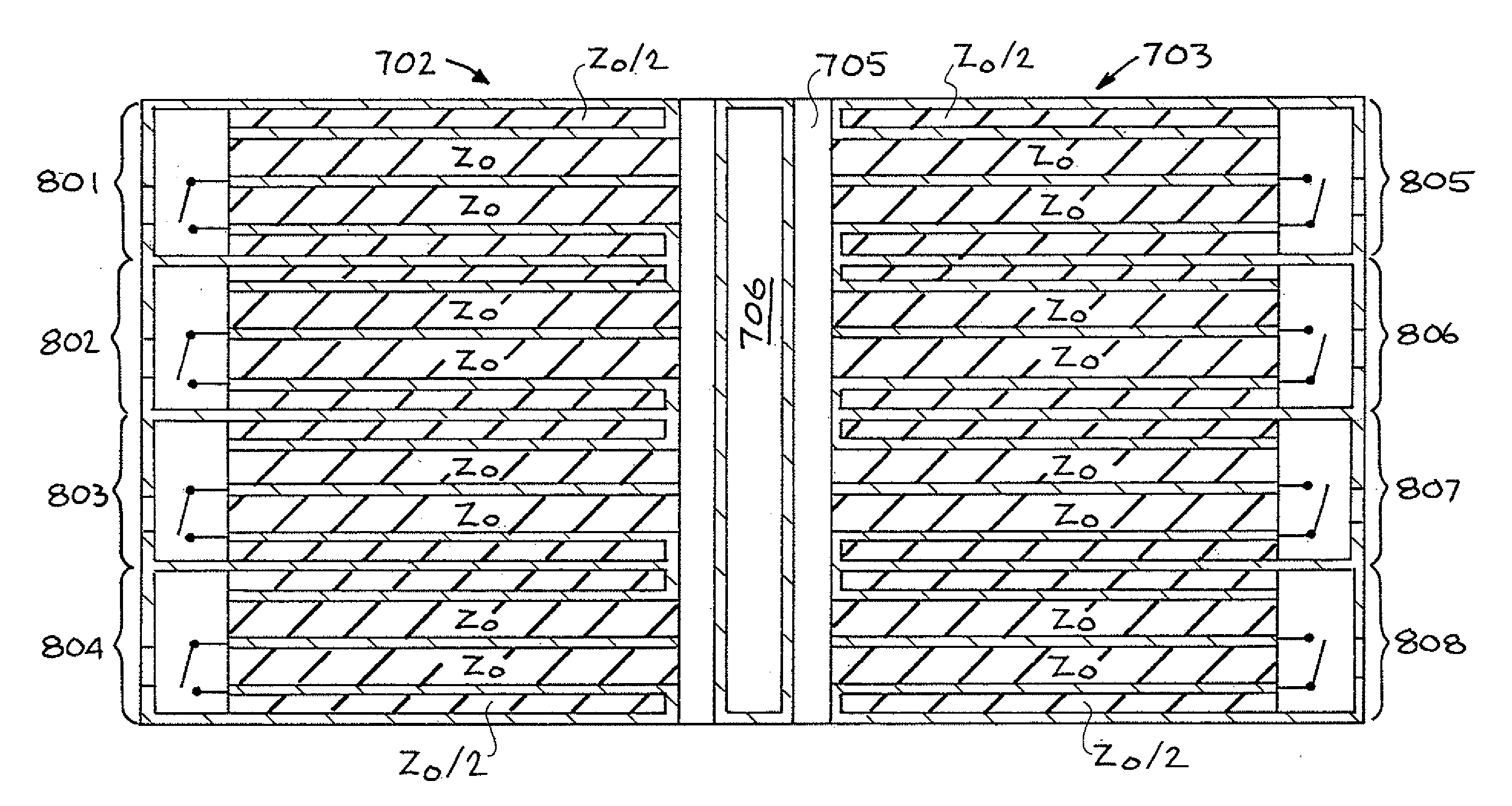
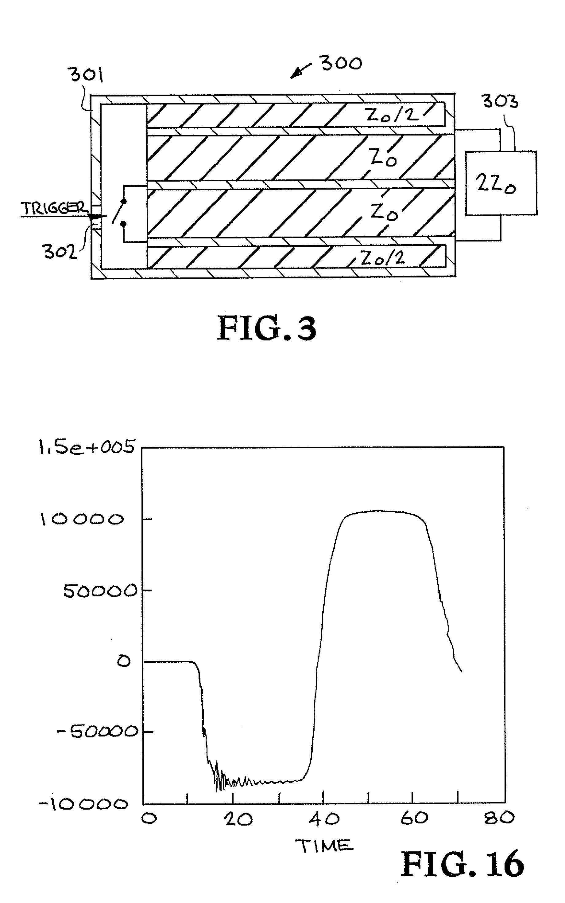
[0028]The present invention pertains to a magnetic-core-free induction LINAC geometry that is based on a parallel-plate transmission line, stacked Blumlein-like structure which produces a symmetric bipolar, zero integral output voltage pulse into a matched load that appears during the second half of the voltage cycle. As such, while the structure is surrounded by a groundable metal boundary it does not require a magnetic core to keep the metal boundary from shorting the output and is, in theory, 100% efficient into a matched load. Furthermore, the structure has a “wraparound” configuration of the shorted-line section which shortens the overall span (e.g. radial span) of the structure, and enables facilitated access to an internal switch region within the structure cavity. The present invention may be utilized in compact linear induction accelerator (LIA) structures for a variety of applications.

[0029]Turning now to the drawings, FIG. 2 show a first exemplary structure of the bipolar...


PUM


Abstract

A bipolar pulse forming transmission line module and system for linear induction accelerators having first, second, third, and fourth planar conductors which form a sequentially arranged interleaved stack having opposing first and second ends, with dielectric layers between the conductors. The first and second planar conductors are connected to each other at the first end, and the first and fourth planar conductors are connected to each other at the second end via a shorting plate. The third planar conductor is electrically connectable to a high voltage source, and an internal switch functions to short at the first end a high voltage from the third planar conductor to the fourth planar conductor to produce a bipolar pulse at the acceleration axis with a zero net time integral. Improved access to the switch is enabled by an aperture through the shorting plate and the proximity of the aperture to the switch.

Description

CROSS-REFERENCE TO RELATED APPLICATIONS[0001]This application is a continuation-in-part of application Ser. No. 11 / 450,429, filed Jun. 9, 2006, which claims the benefit of provisional Application No. 60 / 689,635 filed Jun. 9, 2005. This application also claims priority in provisional Application No. 60 / 936,256, filed Jun. 18, 2007, incorporated by reference herein.FEDERALLY SPONSORED RESEARCH OR DEVELOPMENT[0002]The United States Government has rights in this invention pursuant to Contract No. DE-AC52-07NA27344 between the United States Department of Energy and Lawrence Livermore National Security, LLC for the operation of Lawrence Livermore National Laboratory.FIELD OF THE INVENTION[0003]The present invention relates to bipolar pulse generators and more particularly to a bipolar pulse forming transmission line having a single unsplit shorted-line wrapped around one side of the transmission line.BACKGROUND OF THE INVENTION[0004]Electron-beam induction accelerators, such as linear ind...

Claims


Application Information

Patent Timeline
Patent Type & Authority Applications(United States)
IPC IPC(8): H01J19/80H01J7/46H03K3/00H03K3/64
CPCH03K3/53H05H7/02
Inventor RHODES, MARK A.
Owner LAWRENCE LIVERMORE NAT SECURITY LLC
Learn More