Method of Setting the Origin of a Linear Motor

Inactive Publication Date: 2008-10-30
WAKO GIKEN
View PDF5 Cites 22 Cited by
  • Summary
  • Abstract
  • Description
  • Claims
  • Application Information

AI Technical Summary

Benefits of technology

[0013]It is an object of the present invention to provide a method of setting and establishing an origin, bo

Problems solved by technology

However, they cannot detect the absolute position of the member (i.e., the position the member assumes with respect to a coordinate origin).
In linear motors using an optical linear encoder, the detection sensibility of t

Method used


Image

  • Method of Setting the Origin of a Linear Motor
  • Method of Setting the Origin of a Linear Motor
  • Method of Setting the Origin of a Linear Motor

Examples


Embodiment Construction

[0035]Throughout this description, the embodiments and examples shown should be considered as exemplars, rather than limitations on the apparatus and methods of the present invention.

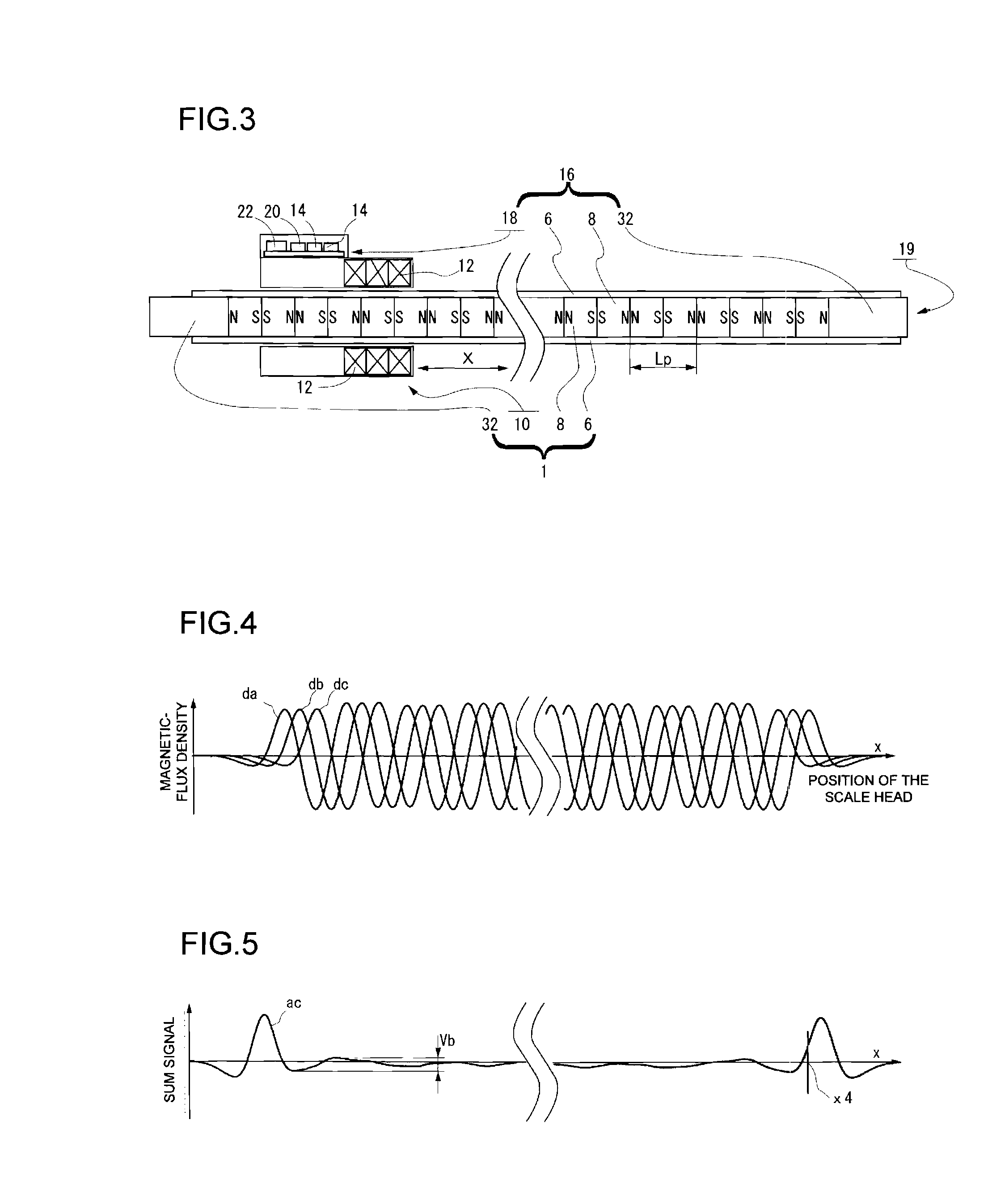
[0036]Embodiments of the present invention will be described with reference to the accompanying drawings. In each figure, the components identical to those shown in any other figure are designated by the same reference numerals. Any component that has once been described will not be explained again. In any linear motor according to this invention, the field yoke or the armature is secured to the stator, while the other is used as movable member. Thus, the field yoke and the armature are moved relative to each other in a straight line. In the embodiments that will be described below, the field yoke is fixed to the stator and the armature is used as movable member, for the convenience of explanation. The present invention is not limited to these embodiments, nonetheless.

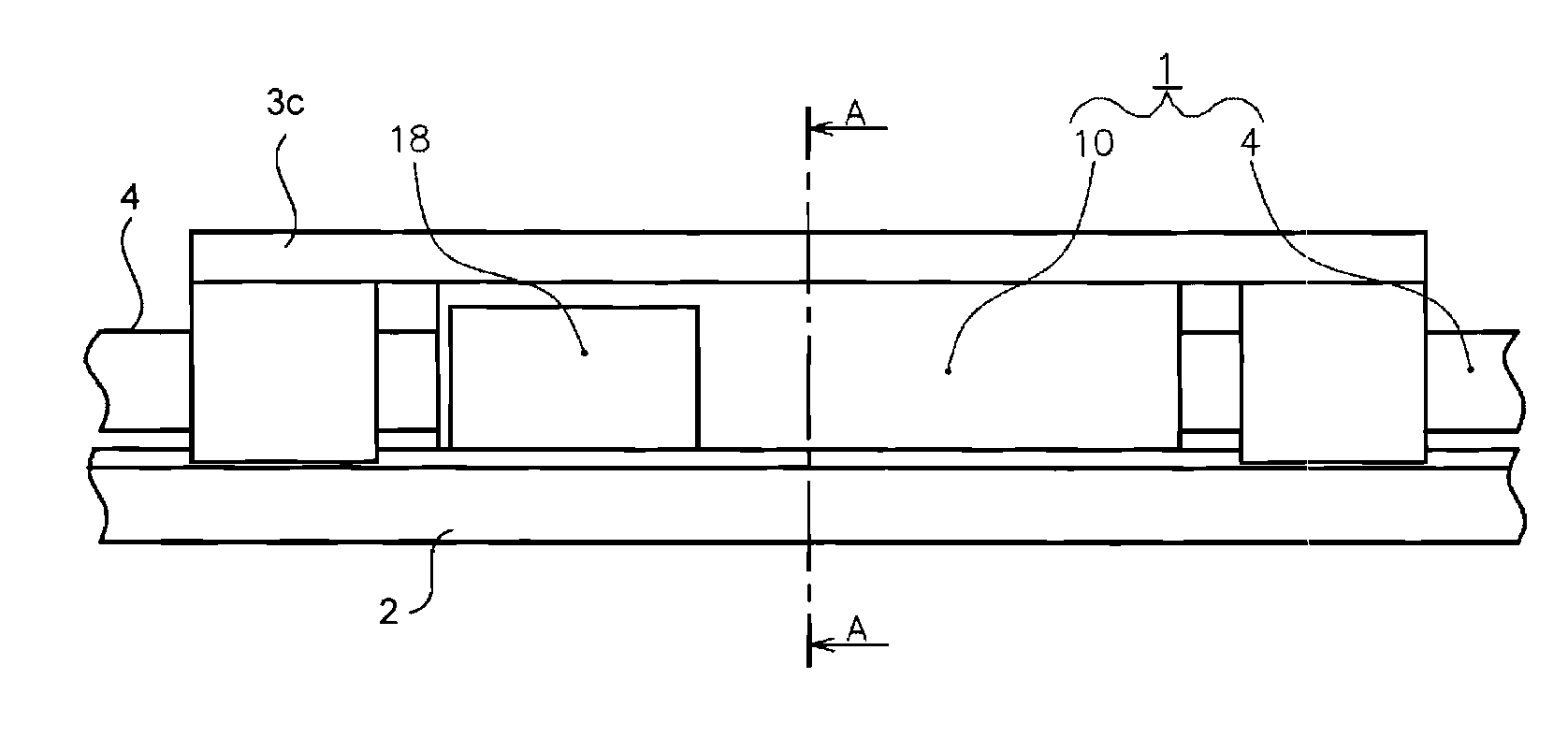
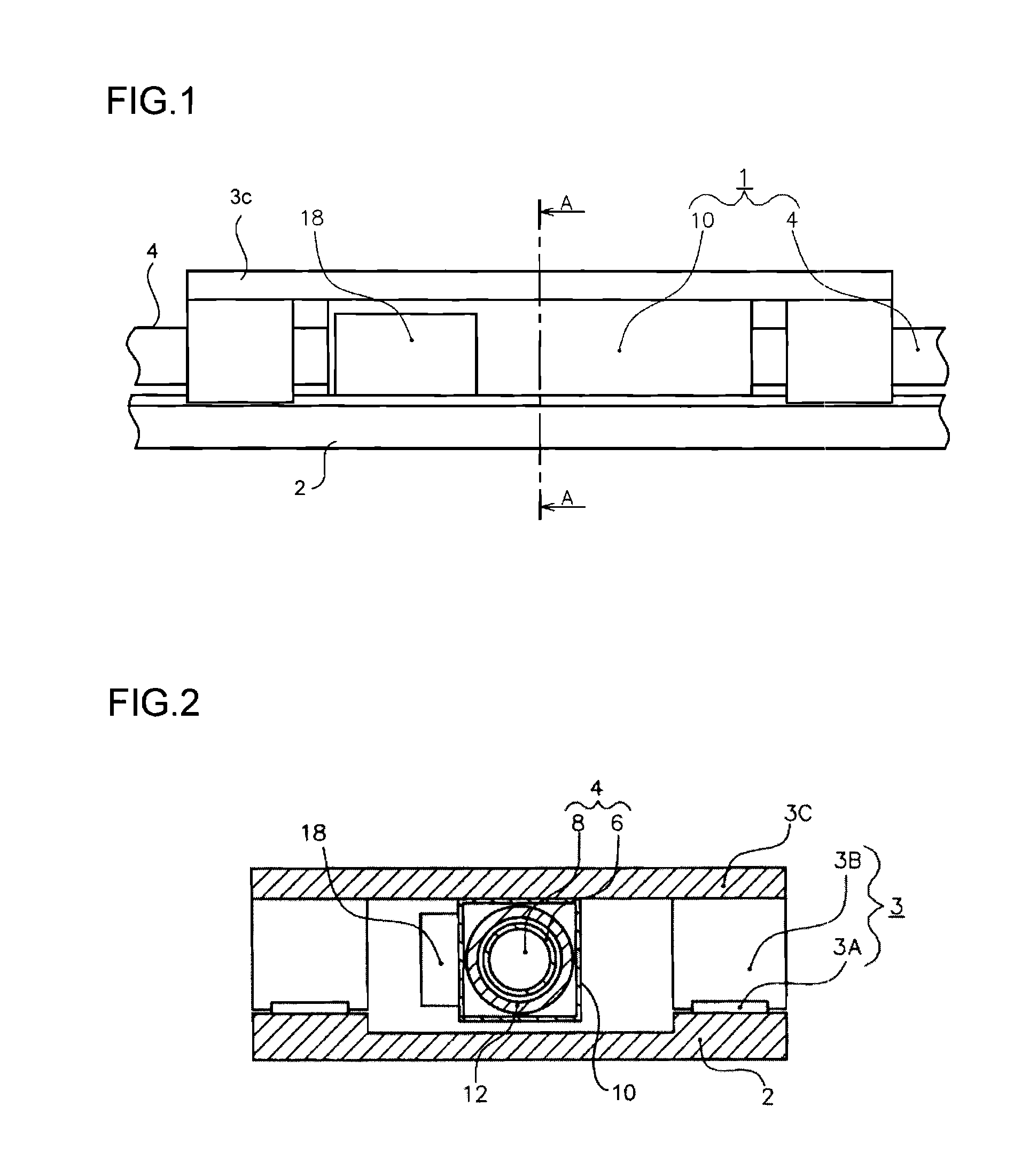
[0037]FIG. 1 is a front view outlin...


PUM


Abstract

A movable member is moved in a preset direction in a linear motor. A characteristic-change position-detecting unit detects a position where the magnetic characteristic of the magnets has abruptly changed. The position detected is used as an origin-setting reference position. A reference position for the absolute position of the magnetic linear encoder is set based on the reference position.

Description

CROSS-REFERENCE TO RELATED APPLICATIONS[0001]This application is based upon and claims the benefit of priority from the prior Japanese Patent Applications No. 2007-121942 filed on Apr. 5, 2007, No. 2007-131033 filed on Apr. 17, 2007 and No. 2008-061141 filed on Mar. 11, 2008, the entire contents of which are incorporated herein by reference.BACKGROUND OF THE INVENTION[0002]1. Field of the Invention[0003]The present invention relates to a method of setting the origin of a linear motor. More particularly, the invention relates to a method of setting an origin in a linear motor that incorporates a magnetic linear encoder used as high-speed repeated positioning means.[0004]2. Description of the Related Art[0005]Linear motors are used as drive sources in many transfer mechanisms and transporting mechanisms. When a linear motor is used, it is necessary to detect where the movable member is moving in the linear motor. A linear encoder is used as means for detecting the position of the mova...

Claims


Application Information

Patent Timeline
IPC IPC(8): G05B11/00
CPCG01D5/2013G01D5/2457H02K11/0021H02K2213/03H02K1/2713H02K1/28H02K41/031H02K11/215
Inventor SASAKI, TOSHIHIKOWATANABE, KAZUOISHIKAWA, KATSUMI
Owner WAKO GIKEN
Why Eureka
Try Eureka