Resistive heating element for enabling laser operation

Active Publication Date: 2008-10-30
II VI DELAWARE INC
View PDF14 Cites 10 Cited by
  • Summary
  • Abstract
  • Description
  • Claims
  • Application Information

AI Technical Summary

Benefits of technology

[0009]In one embodiment, a laser package is disclosed. The laser package includes a substrate. A laser is disposed on the substrate. A resistive heating element is disposed on the substrate with the laser. Control circuitry is connected to the resistive heating element. The co

Problems solved by technology

Operation outside of the temperature range can reduce the laser's performance to the point it is unusable.
This may give rise a host of problems for laser operation.
Illustratively, operation at colder temperatures may cause the laser's reaction speed, the speed at which the laser changes from high power output to low pow

Method used


Image

  • Resistive heating element for enabling laser operation
  • Resistive heating element for enabling laser operation

Examples


Example

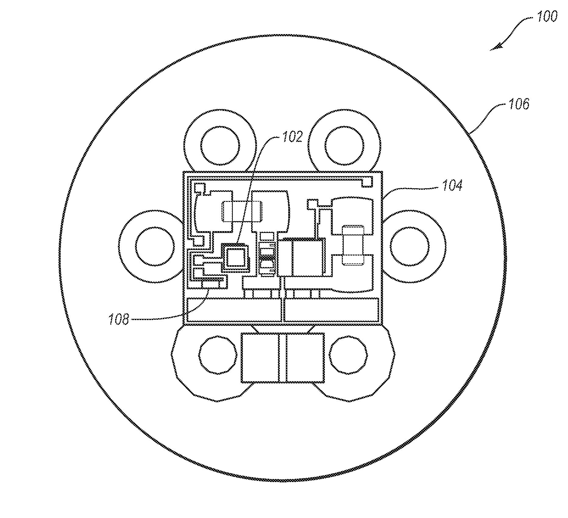
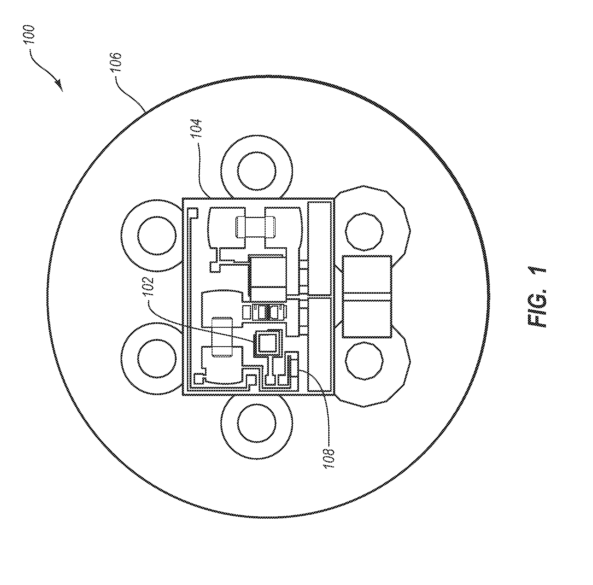
[0015]One embodiment described herein is directed to expanding the range in which a laser assembly, such as a transmitter optical sub-assembly (TOSA) or other laser package, including a laser, may be operated. In particular, one embodiment includes a resistive heating element disposed on the same substrate as the laser in the TOSA. A determination can be made as the ambient temperature of the operating environment for the TOSA. If the ambient temperature is below some pre-determined temperature, current can be passed through the resistive heating element. Heat is transferred to the laser through the substrate to raise the operating temperature of the laser. Current through the resistive heating element can be adjusted depending on the temperature difference between the actual ambient temperature and an ideal ambient temperature.

[0016]Modern day computer networks allow for transmissions of large amounts of data between computer terminals. Data may be transmitted on a network across a...


PUM


Abstract

Heating resistor used to control laser operation. A laser package, such as a Transmitter Optical Subassembly (TOSA) includes a substrate. A laser is disposed on the substrate. A resistive heating element is disposed on the substrate with the laser. Control circuitry is connected to the resistive heating element. The control circuitry is configured to cause current flow through the resistive heating element based on temperature conditions. Current flow through the resistive heating element causes an increase in the operating temperature of the laser. This can be used to increase the effective operating temperature range of a laser.

Description

BACKGROUND OF THE INVENTION[0001]1. The Field of the Invention[0002]The invention is generally directed to optimizing laser operating environments. In particular, the invention is directed to heating a laser to allow the laser to operate in an acceptable temperature range.[0003]2. Description of the Related Art[0004]Lasers are commonly used in many modem components. One use that has recently become more common is the use of lasers in data networks. Lasers are used in many fiber optic communication systems to transmit digital data on a network. In one exemplary configuration, a laser may be modulated by digital data to produce an optical signal, including periods of light and dark output that represents a binary data stream. In actual practice, the lasers output a high optical output representing binary highs and a lower power optical output representing binary lows. To obtain quick reaction time, the laser is constantly on, but varies from a high optical output to a lower optical ou...

Claims


Application Information

Patent Timeline
IPC IPC(8): H01S3/04H01S5/12
CPCH01S5/02212H01S5/02284H01S5/02453H01S5/0261H01S5/12H01S5/183H01S5/02251
Inventor DENG, HONGYUKALBERER, MARTIN ANDRE
Owner II VI DELAWARE INC
Why Eureka
Try Eureka