
Hip fracture device with barrel and end cap for load control

a technology of femur fracture and load control, which is applied in the field of appendix and method for the treatment of proximal femur fracture, can solve the problems of undesired femur shortened neck

Active Publication Date: 2008-10-30
STRYKER EURO OPERATIONS HLDG LLC
View PDF99 Cites 36 Cited by
  • Summary
  • Abstract
  • Description
  • Claims
  • Application Information

AI Technical Summary

Benefits of technology

[0012]Another aspect of the invention is a method of repairing a fracture between the head and neck of a femur. The method includes the steps of affixing a plate having a head portion and a shaft portion on the femur, the plate having openings in the head portion and the shaft portion. A barrel is inserted in the opening in the head portion and a screw is inserted in the barrel. An end cap is inserted in the opening having the barrel inserted therein, and a friction pin is inserted between the end cap and the screw. The screw can slide over the friction pin and towards the end cap, and the load required for further sliding of the screw over the friction pin increases incrementally as the screw slides towards the end cap.

Problems solved by technology

One shortcoming of dynamic compression screws is that unless the travel is appropriately limited, the neck of the femur may be undesirably shortened.

Method used


Image

  • Hip fracture device with barrel and end cap for load control
  • Hip fracture device with barrel and end cap for load control
  • Hip fracture device with barrel and end cap for load control

Examples


Embodiment Construction

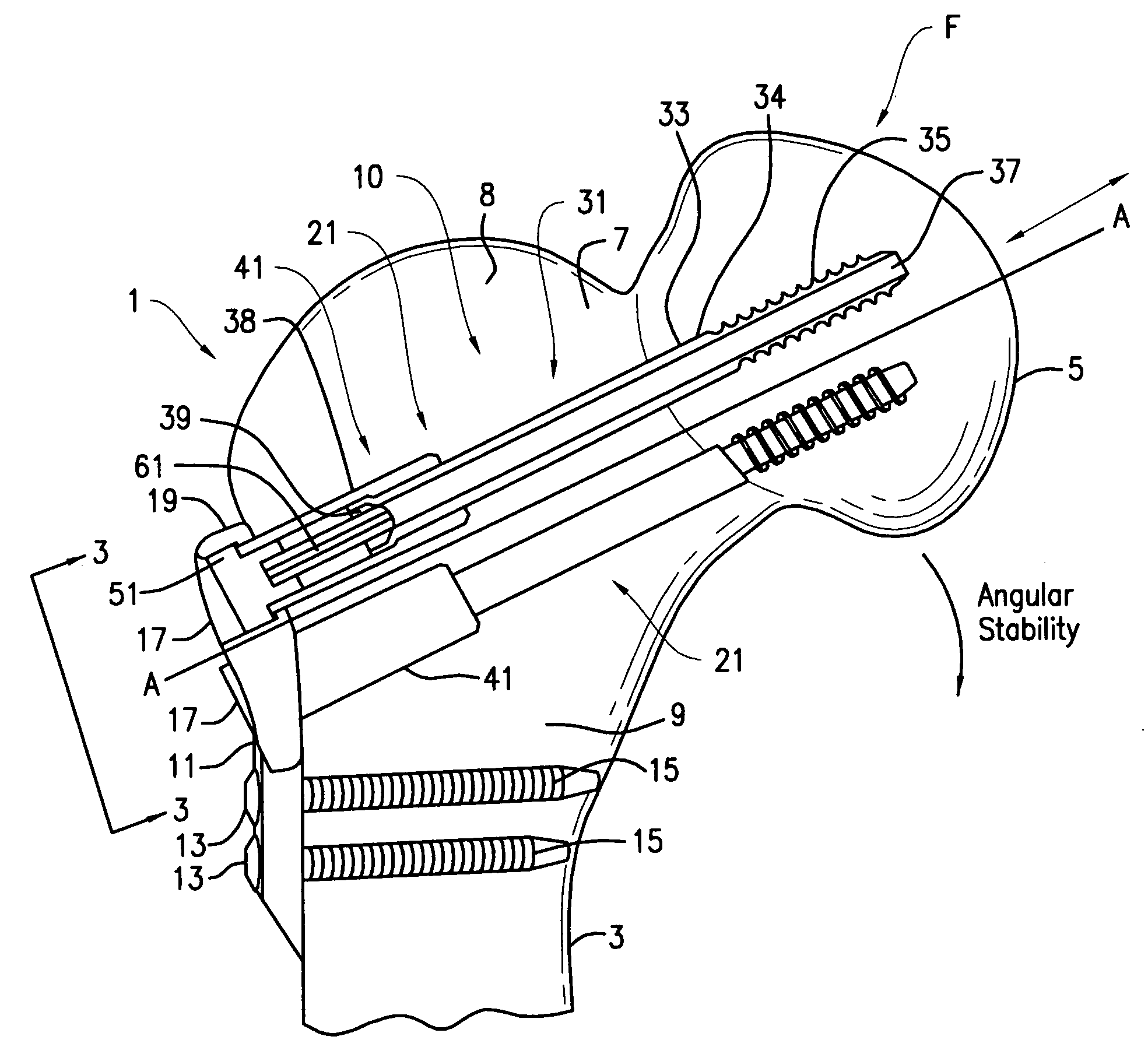
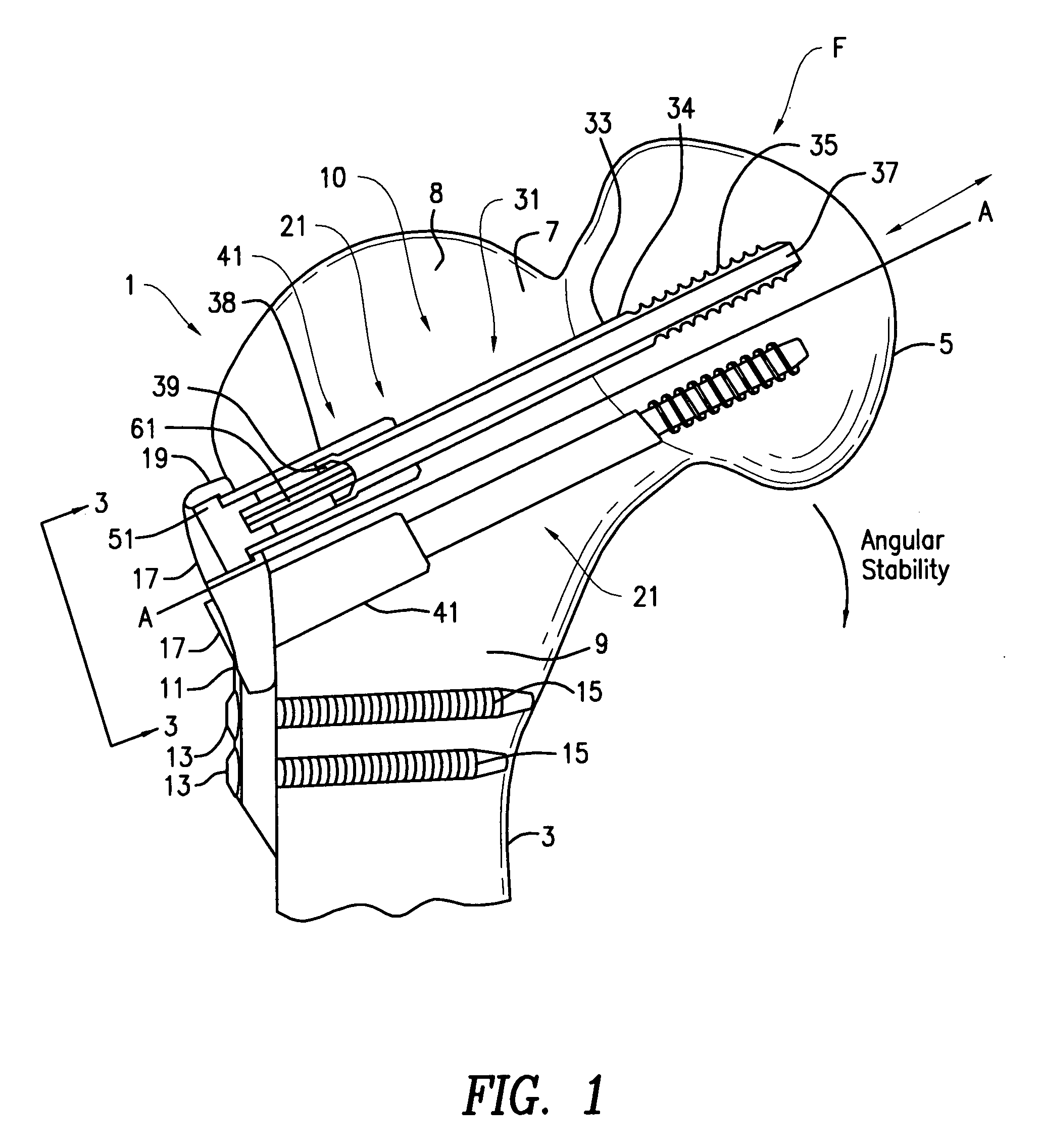
[0025]Referring to FIG. 1, a hip fracture device 21 includes a locking plate 11 and one of more (preferably three) screw assemblies 31. The hip fracture device 21 may be used for fixing bone fractures, particularly femoral neck fractures including Gaarden III / IV type fractures.

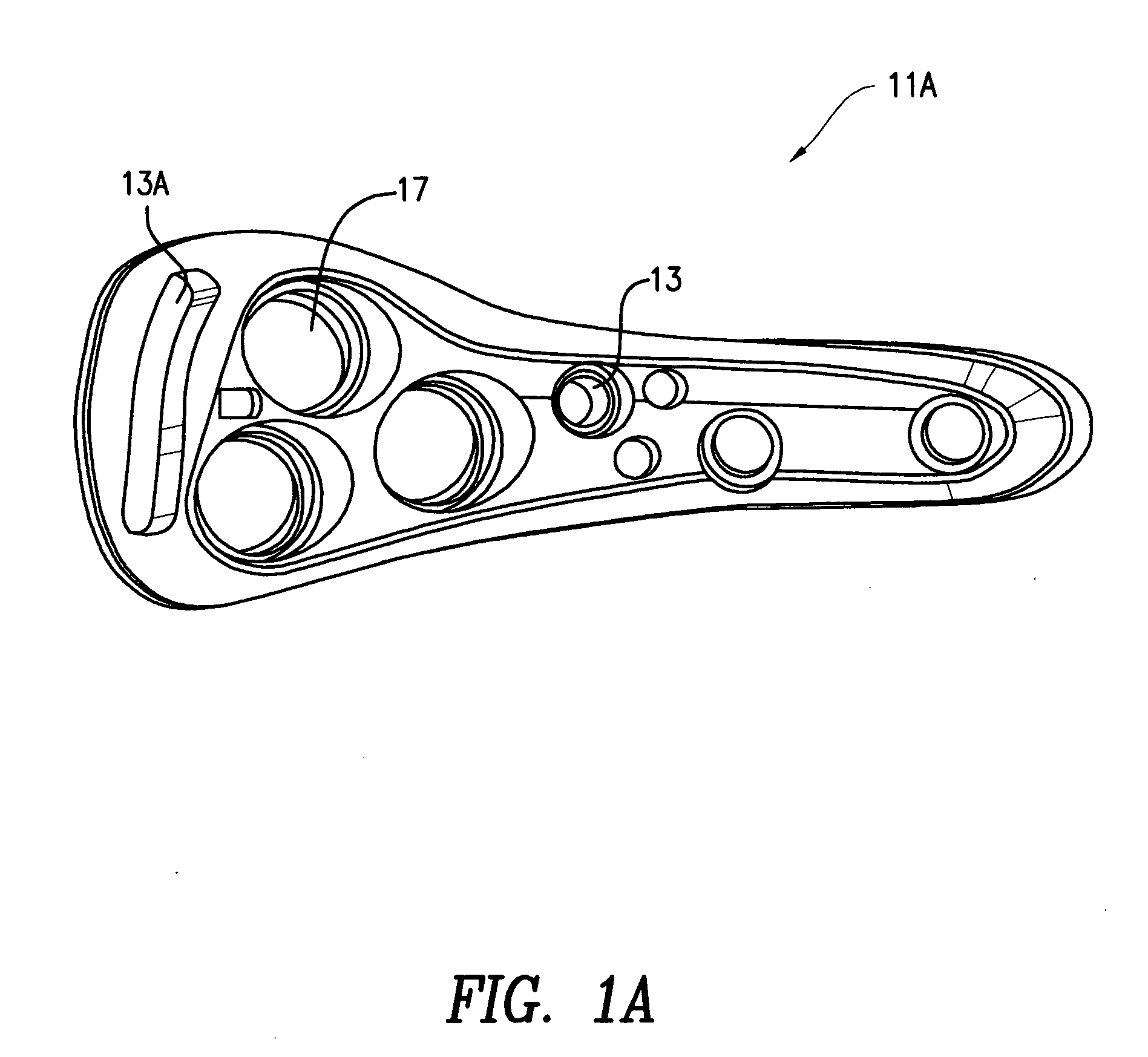
[0026]The locking plate 11 generally conforms to the lateral portion of the proximal femur 1 and is attached to the femur by at least one cortical interlocking screw 15 passing through holes 13 in the subtrochanteric shaft region 3 of the femur 1. The interlocking screws 15 serve to attach the plate 11 to the femur 1. The plate 11 also has one or more stepped bores 17 for each screw assembly 31. The major diameter of the stepped bore 17 incorporates a screw thread for fastening the screw assembly 31. The minor diameter of the stepped bore 17 creates a shoulder 19 at the junction of the major and minor diameters. Each stepped bore 17 is aligned with the axis of each of the screw assemblies 31. FIG. 1A shows a p...


PUM


Abstract

A hip fracture device providing distance limited dynamization, load controlled dynamization and combinations of both dynamization methods by varying components. The hip fracture device includes a plate having a head portion and a shaft portion. A barrel projects from the head portion of the plate and a screw is inserted in the barrel. A friction pin is slidably connected with the screw, and an end cap is fixed to the head portion of the plate. The friction pin is fixedly connected with the end cap. The screw slides over the friction pin and toward the end cap when a load is applied on the fracture device. The load required for further sliding of the screw over the friction pin increases incrementally as the screw slides towards the end cap.

Description

CROSS-REFERENCE TO RELATED APPLICATION[0001]This application claims the benefit of the filing date of U.S. Provisional Patent Application No. 60 / 925,399 filed Apr. 19, 2007, the disclosure of which is hereby incorporated herein by reference.FIELD OF THE INVENTION[0002]The present invention relates generally to an apparatus and method for the treatment of fractures of the proximal femur including the neck of the femur and the intertrochantric region.BRIEF DESCRIPTION OF THE PRIOR ART[0003]Referring to FIG. 1, the femur 1, otherwise known as the thigh bone, generally comprises an elongate shaft extending from the hip to the knee. The proximal end of the shaft 3 includes a head 5, a neck 7, a greater trochanter 8 and a lesser trochanter 9. Internal fixation of femoral fractures in general is one of the most common orthopedic surgical procedures. Fractures of the proximal portion of the femur (hip fractures) generally include femoral neck fractures and intertrochanteric fractures. Fract...

Claims


Application Information

Patent Timeline
IPC IPC(8): A61B17/56A61B17/70A61B17/58
CPCA61B17/746A61B17/8685A61B2017/00858
Inventor SIMON, BERNDKEMPER, JAKOBHOFFMANN, CARSTEN
Owner STRYKER EURO OPERATIONS HLDG LLC
Learn More