AI technical title is built by Patsnap AI team. It summarizes the technical point description of the patent document.
a flexible, expandable technology, applied in the field of stents, can solve the problems of not being a very strong connector, most likely harmful to the blood vessel, etc., and achieve the effect of increasing the width and constant stent cell area
Inactive Publication Date: 2008-10-30
MEDINOL LTD
View PDF4 Cites 5 Cited by
Summary
Abstract
Description
Claims
Application Information
AI Technical Summary
This helps you quickly interpret patents by identifying the three key elements:
Problems solved by technology
Method used
Benefits of technology
Benefits of technology
[0008]The pair of facing loops and the curved flexible links are disposed and adapted to cooperate so that the tube, when unexpended, can flex as it is moved through curved blood vessels to a site where it is to be expanded and so that, when the stent is expanded in a curved vessel, at that site, as compared to each other, cells on the outside of the curve are open in length, but narrow in width as compared to cells on the inside of the curve which are short in length but increased in width. This results in a more constant stent cell area between the inside and the outside of the curve than would otherwise occur. Consequently, when the stent is coated with a medicine the compensation results in a more even dose being applied to the inside wall of the lumen, avoiding the possibility that a toxic dose is supplied at one area while a less than effective dose is applied to another area.
Problems solved by technology
The twisting motion is most probably harmful to the blood vessel.
The straight member removes the twisting motion; however, it is not a very strong connector.
Method used
Image
Click on the blue label to locate the original text in one second.
Reading with bidirectional positioning of images and text.
Examples
Embodiment Construction
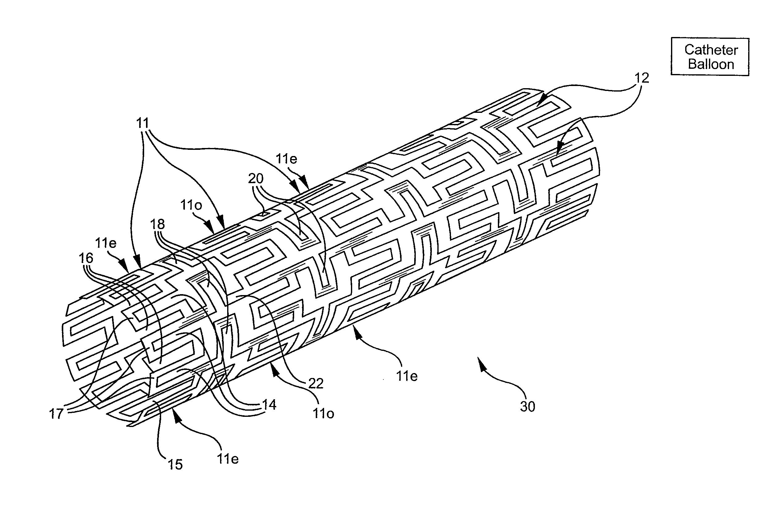
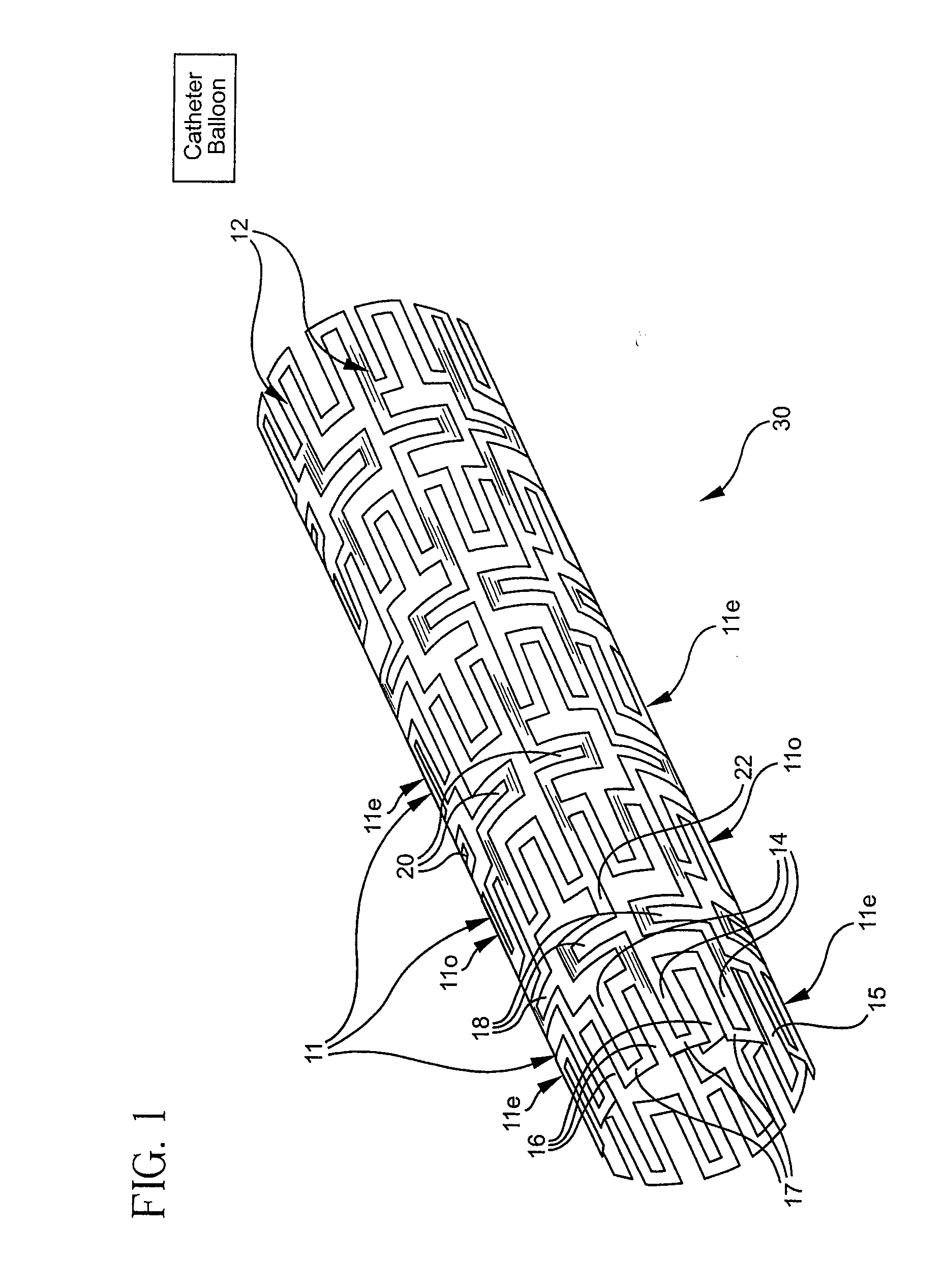
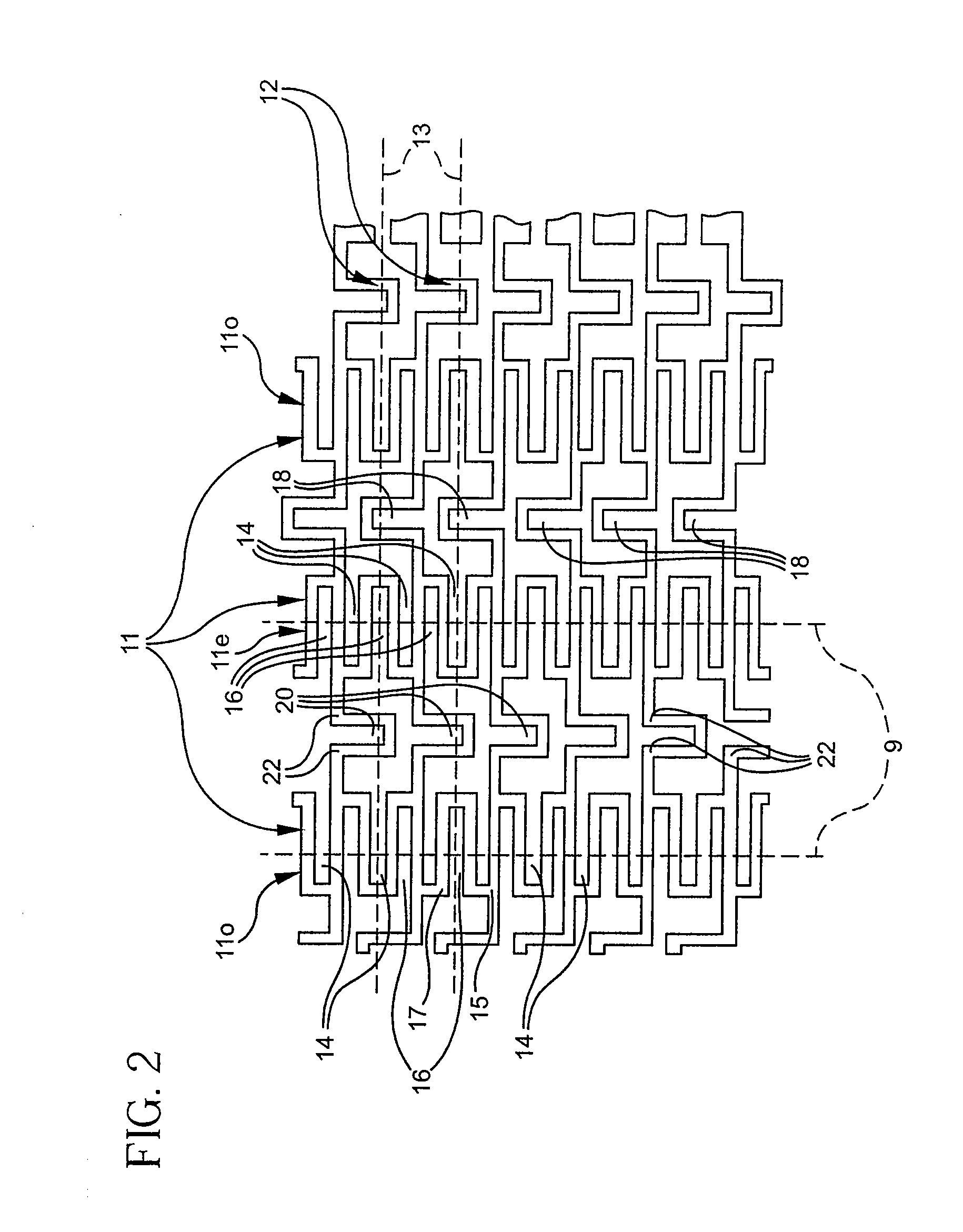
[0018]Reference is now made to FIGS. 1-4 which illustrate a first embodiment of a stent, constructed and operative in accordance with the principles of the present invention. FIG. 1 illustrates the stent in its non-expanded form, FIG. 2 illustrates the pattern of the stent, FIG. 3 illustrates it in a partially bent position and FIG. 4 illustrates it in an expanded form. As shown in FIG. 3, the stent 30 defines a longitudinal aperture 80 having a longitudinal axis or longitudinal extension 79.
[0019]The stent of the present invention is a tube whose sides are formed into a plurality of each of two orthogonal meander patterns which patterns are intertwined with each other. The term “meander pattern” is taken herein to describe a periodic pattern about center line and “orthogonal meander patterns” are patterns whose center lines are orthogonal to each other.
[0020]In the stent of FIGS. 1-4, the two meander patterns are labeled 11 and 12 and they are most easily seen in FIG. 2. Meander pa...
PUM
Abstract
A stent for implanting in the body to hold open a blood vessel includes cells with facing loops and the curved flexible links disposed and adapted to cooperate so that, when unexpanded, the stent can flex as it is moved through curved blood vessels to a site where it is to be expanded and so that, when the stent is expanded in a curved vessel, at that site, as compared to each other, cells on the outside of the curve are open in length, but narrow in width as compared to cells on the inside of the curve which are short in length but increased in width to result in a more constant stent cell area between the inside and the outside of the curve than would otherwise occur causing the stent, when coated with a medicine, to apply a more even dose to the inside wall of the lumen, avoiding the possibility that a toxic dose is supplied at one area while a less than effective dose is applied to another area.
Description
RELATED APPLICATIONS[0001]This application is a continuation of Ser. No. 09 / 337,629 filed Jun. 21, 1999, which is a continuation of Ser. No. 09 / 026,099 filed Feb. 19, 1998 (now U.S. Pat. No. 5,972,018), which is a continuation of Ser. No. 08 / 881,594 filed Jun. 24, 1997 (now U.S. Pat. No. 5,843,120), which is a continuation of Ser. No. 08 / 782,467 filed Jan. 10, 1997, now abandoned, which is a continuation of Ser. No. 08 / 457,354, filed May 31, 1995 (now U.S. Pat. No. 5,733,303), which is a continuation of Ser. No. 08 / 282,181 filed Jul. 28, 1994 (now abandoned) and a continuation-in-part of Ser. No. 08 / 213,272, filed Mar. 17, 1994 (now U.S. Pat. No. 5,449,373).FIELD OF THE INVENTION[0002]The present invention relates generally to stents for implanting into a living body.BACKGROUND OF THE INVENTION[0003]Various stems are known in the art wherein, for the present application, the term “stent” indicates a device, made of body-compatible material, which is utilized to widen a blood vessel,...
Claims
Application Information
Patent Timeline
Application Date:The date an application was filed.
Publication Date:The date a patent or application was officially published.
First Publication Date:The earliest publication date of a patent with the same application number.
Issue Date:Publication date of the patent grant document.
PCT Entry Date:The Entry date of PCT National Phase.
Estimated Expiry Date:The statutory expiry date of a patent right according to the Patent Law, and it is the longest term of protection that the patent right can achieve without the termination of the patent right due to other reasons(Term extension factor has been taken into account ).
Invalid Date:Actual expiry date is based on effective date or publication date of legal transaction data of invalid patent.
Patent Type & AuthorityApplications(United States)

