Combination Ball Clip and Ball Liner and Ball Clip for use with a Ball Liner

a ball clip and ball liner technology, applied in the field of ball liner, can solve the problems of not being able to accurately check the position of the ball through the line or mark the hole of the semi-spherical top cover when using, and the ball line maker cannot help the user draw an endless horizontal line,

Inactive Publication Date: 2008-11-06
SUNG MIN HSIEN
View PDF13 Cites 13 Cited by
  • Summary
  • Abstract
  • Description
  • Claims
  • Application Information

AI Technical Summary

Benefits of technology

[0010]The present invention has been accomplished under the circumstances in view. It is one object of the present invention to provide a ball clip for use with a ball liner, which holds down a golf ball firmly in the ball liner, enabling the user to mark guidelines on the golf ball positively and accurately. It is another object of the present invention to provide a combination ball clip and ball liner, which includes a ball liner for marking a club head guideline, a directional guide line and a 360° horizontal guideline on a golf ball, and a ball clip for holding down a golf ball in the ball liner for marking guidelines.
[0013]The ball clip is easy to operate. The ball clip has a simple structure that saves much material. Therefore, the ball clip is inexpensive to manufacture. By means of the ball clip, the gold ball that is put in the ball liner is firmly secured in place for marking guidelines. When the user is marking a guideline on the golf ball, the golf ball does not rotate in the ball liner. In case of an interruption when marking a guideline, the user can draw a perfect guideline when resume marking the guideline. Further, the hollow mounting block is directly attached to the border edge of the ball line without any fastener, and the positioning of the hollow mounting block on the ball liner does not hinder the user from using the ball liner to mark guidelines on a golf ball. Frequently turning the smoothly arched clip body between the ball-holding position and the ball-releasing position does not cause the ball clip to wear. Simply by lifting the smoothly arched clip body from the ball-holding position to the ball-releasing position, the position of the golf ball in the ball liner can then be adjusted.
[0014]Further, by means of the ball liner, the user can draw a directional guideline on a golf ball after check of the center of gravity of the golf ball. The user can also draw a 360° guideline on a golf ball along the seam of the golf ball. By means of the guidance of the 360° guideline, the user can accurately control the balance of the rotation of the golf ball when putting the golf ball on the green toward the hole.
[0016]Further, when the ball clip is fastened to the ball liner, the front end of the smoothly arched clip body is kept spaced from the annular scale of the ball liner. Therefore, the user can draw a 360° guideline around the circumference of the golf ball without interruption.
[0017]The invention can also help a golf game beginner in a golf practice yard to visually aim the contact between the golf ball and the golf club at the target. When the contact angle between the golf ball and the golf club is checked, the user can then check the performance and find the problem in hitting the ball.

Problems solved by technology

Further, this design of ball line maker cannot help the user draw an endless horizontal line, or multiple lines in different directions at one cycle.
Further, the ball line marker cannot help the user draw connected lines, or an endless line around the periphery of the ball.
Although the semispherical base has a circular bottom adjustment hole for the insertion of a finger to rotate the ball and to further adjust the position of the ball in the semispherical base, the use still cannot accurately check the position of the ball through the line or marking holes of the semispherical top cover when rotating the ball in the semispherical base.
However, it does not allows the user to draw other guidelines on a golf ball.
Further, the accommodation hole of the ball line marker cannot hold the loaded golf ball in position.
When marking the golf ball, the golf ball may displace in the accommodation hole, causing interruption of the marking line.
This operation is complicated, wasting much time, and causing the retainer to wear quickly.
For example, when putting a golf ball that has its center of gravity biased from the center of the ball, the center of gravity of the golf ball will affect the direction of rotation of the golf ball, causing the golf ball to move out of the expected path.

Method used


Image

  • Combination Ball Clip and Ball Liner and Ball Clip for use with a Ball Liner
  • Combination Ball Clip and Ball Liner and Ball Clip for use with a Ball Liner
  • Combination Ball Clip and Ball Liner and Ball Clip for use with a Ball Liner

Examples


Embodiment Construction

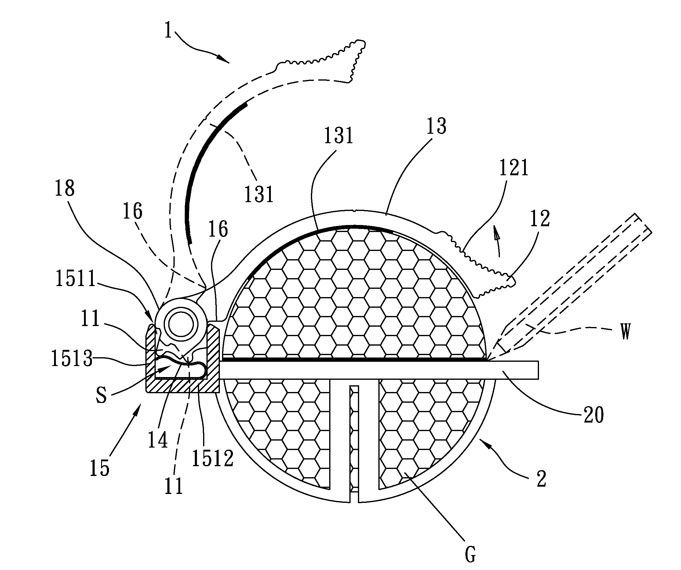
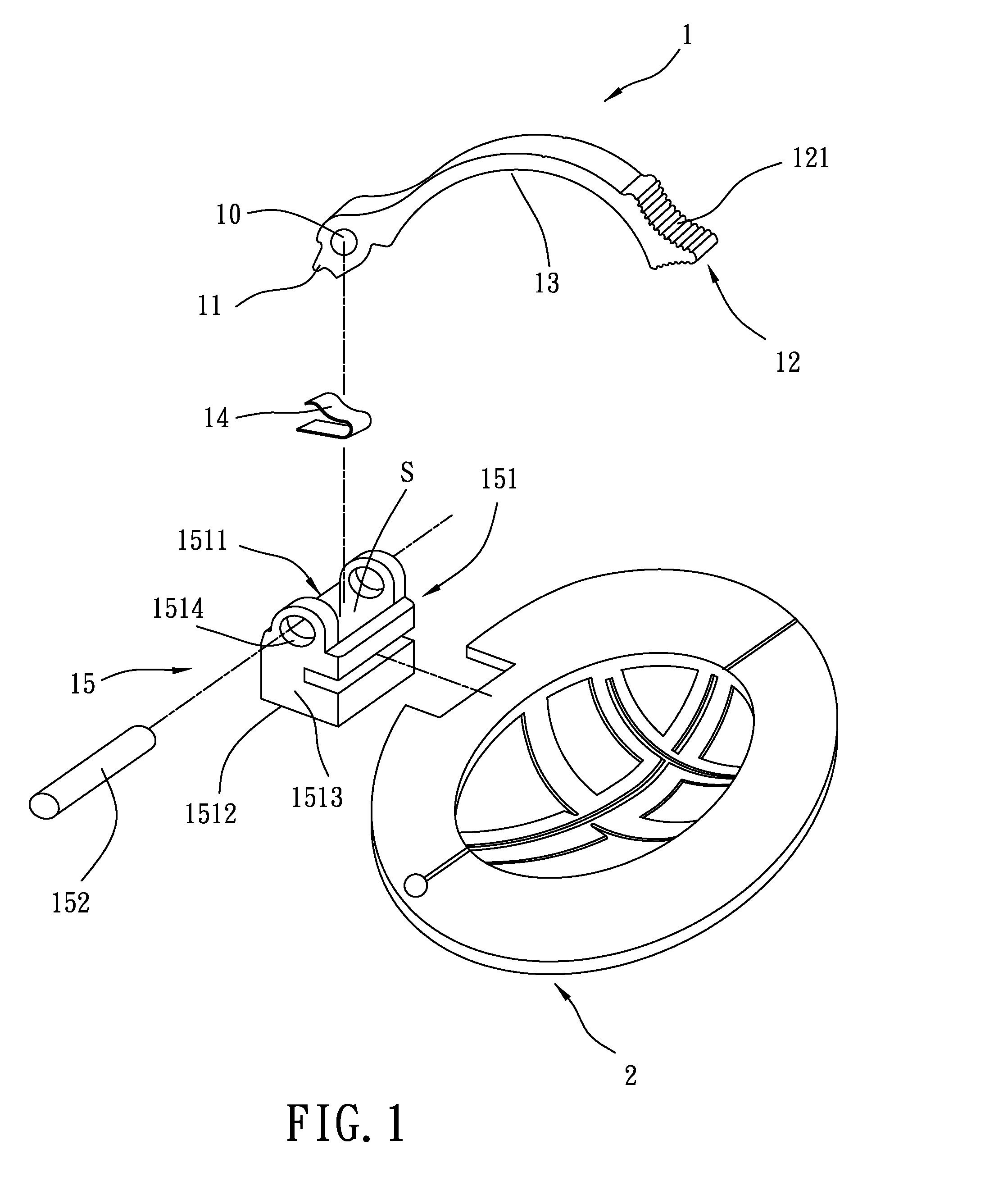
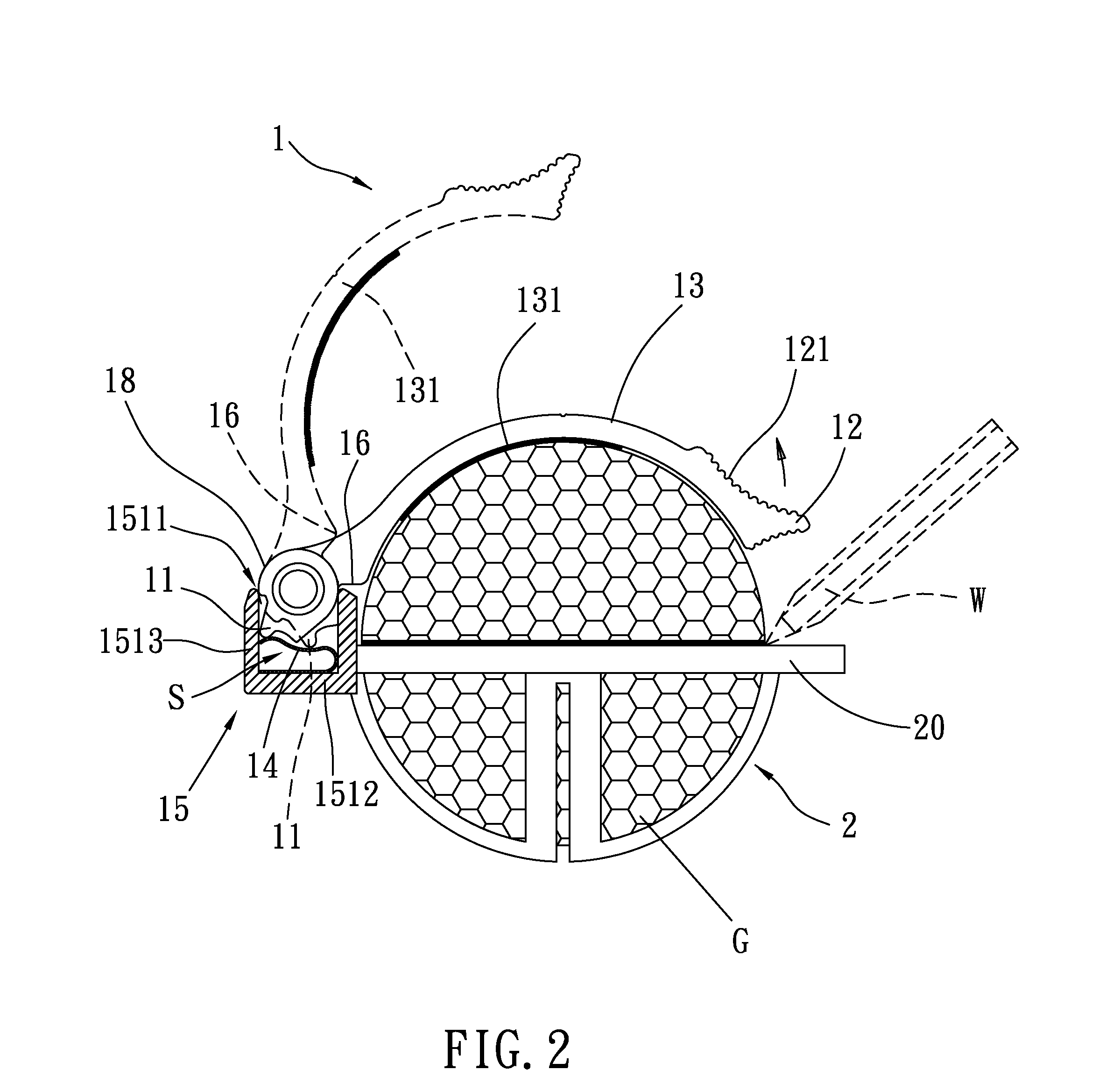
[0033]Referring to FIGS. 1 and 2, a ball clip 1 is shown used with a ball liner 2 for holding down a golf ball G in the ball liner 2 for marking aiming lines. The ball clip 1 comprises a smoothly arched clip body 13, an elastic member 14, and a mounting assembly 15 for securing the clip body 1 to the ball liner 2. The smoothly arched clip body 13 has a grip 12 formed integral with its one end, namely, the front end, a pivot hole 10 transversely cut through its other end, namely, the rear end, and a protruding block 11 protruded from the periphery of its rear end. The mounting assembly 15 is comprised of a hollow mounting block 151 and a pivot pin 152. The hollow mounting block 151 has an opening 1511, a bottom wall 1512, a peripheral wall 1513, an accommodation chamber S surrounded by the bottom wall 1512 and the peripheral wall 1513 and disposed in communication with the opening 1511, and two pivot holes 1514 cut through the peripheral wall 1513 and axially aligned at two sides abo...


PUM


Abstract

A combination ball clip and ball liner includes a ball liner for marking a club head guideline, a directional guide line and a 360° horizontal guideline on a golf ball, and a ball clip for holding down a golf ball in the ball liner for marking guidelines. The ball clip includes a hollow mounting block fastened to the ball liner, a smoothly arched clip body pivoted to the hollow mounting block, and an elastic member mounted in the hollow mounting block to bias the smoothly arched clip body, holding the smoothly arched clip body in the ball-holding position.

Description

[0001]This application is a continuous-in-part application of U.S. patent application Ser. No. 11 / 742,805, filed on May 1, 2007.BACKGROUND OF THE INVENTION[0002]1. Field of the Invention[0003]The present invention relates to a ball liner for marking aiming lines on a golf ball and more particularly, to such a ball liner that is equipped with a ball clip for holding down a golf ball for marking aiming lines.[0004]2. Description of the Related Art[0005]Playing the game of golf brings pleasure and spiritual encouragement, however it requires practice and skill. The keypoint in performing the game of golf is to make sure of the hitting angle. The hitting angle controls the moving direction of the ball. Biasing of the hitting angle will drive the ball out of the course, and the ball will not fall to the expected location. The ball structure, hitting location, hitting angle, club swinging manner are important factors that determine the performance. Therefore, using a scientific method to ...

Claims


Application Information

Patent Timeline
Patent Type & Authority Applications(United States)
IPC IPC(8): G01B3/14A63B57/00
CPCA63B45/02A63B57/00A63B57/20Y10S101/40
Inventor SUNG, MIN HSIEN
Owner SUNG MIN HSIEN
Why Eureka
Try Eureka