Extruded Cushioning Insole

Inactive Publication Date: 2008-11-06
FISCHER JAMES R
View PDF22 Cites 21 Cited by
  • Summary
  • Abstract
  • Description
  • Claims
  • Application Information

AI Technical Summary

Problems solved by technology

The FPVC plastic material retains its compression resistance and resiliency for a ...

Method used


Image

  • Extruded Cushioning Insole
  • Extruded Cushioning Insole
  • Extruded Cushioning Insole

Examples


first embodiment

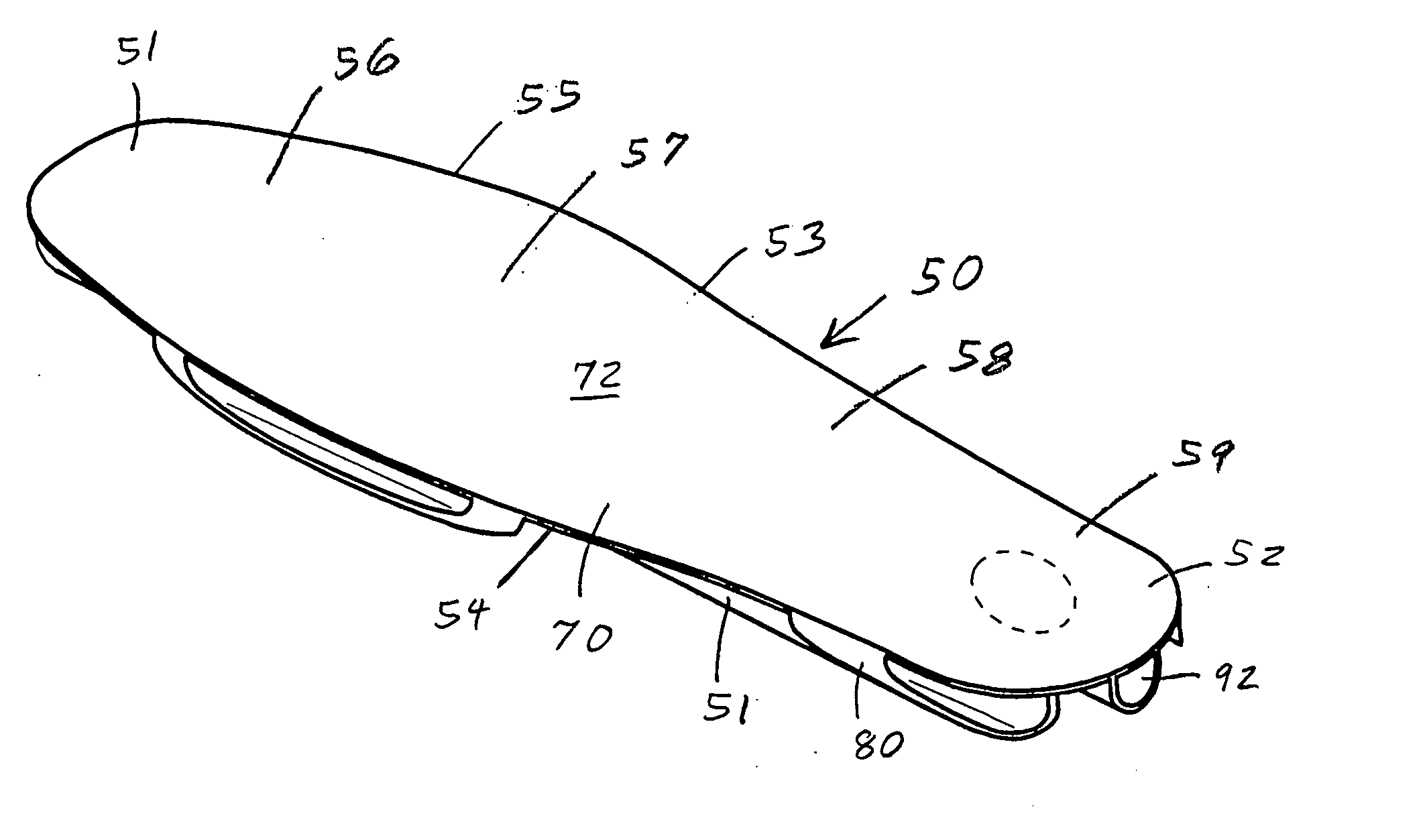
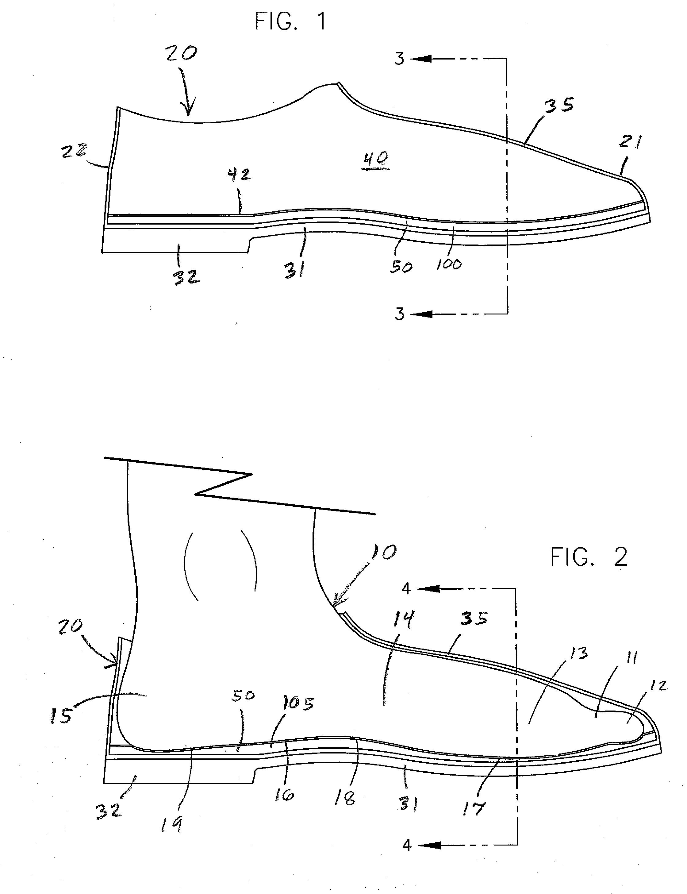
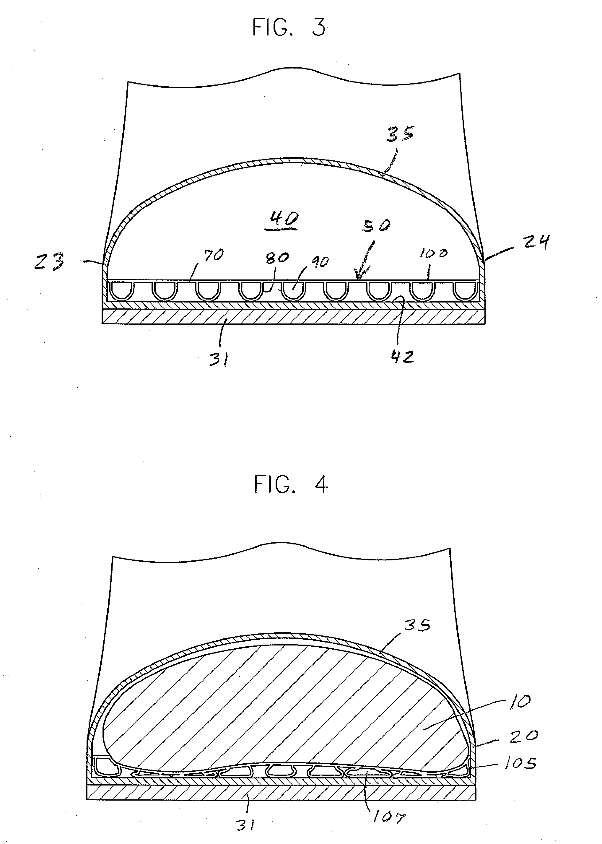
[0056]the insole or insert 50 is shown in FIGS. 3, 4, 6 and 7. This insert 50 has a continuous upper layer 70 and a plurality of hollow, lower tubes 80. The upper layer or flexible pad 70 has a solid body with generally flat, parallel upper and lower surfaces 72 and 74. The layer 70 has a uniform thickness of about 0.06 inch. The upper surface 72 can have a number of upwardly extending, uniformly spaced, gripping ridges, about 10 per inch (not shown) to allow the bottom surface 16 of the foot 10 or a sock to better grip the insert 50. Each ridge has a height of about 0.007 inch. The upper layer 70 is preferably continuous from one end of the insert to the other, and from one side of the insert to the other. The insole 50 can include one or more cutout areas 78 to relieve or avoid pressure from the bottom 16 of the foot 10 in those areas as in FIGS. 6 and 12.

[0057]The tubes 80 project down from and are uniformly spaced across the lower surface 74 of the upper layer 70. Each tube 80 i...

second embodiment

[0061]the insole or insert 150 is shown in FIG. 8. This insert 150 also has a continuous, flexible pad 70 with a uniform thickness of about 0.06 inch, and several evenly spaced conjoined tubes 80. Each tube 80 is formed by a wall 82 having opposed side portions 83 and an arced bottom portion 84. The wall 82 has a uniform thickness of about 0.03 to 0.04 inch. Each tube 80 has a height of about 0.18 inch and a width of about 0.25 inch. The insert 150 has a total relaxed or uncompressed height of about 0.24 inch. Adjacent tubes 80 share a common side portion 83 so there are about 16 longitudinal tubes in a 4 inch wide insole 150. When in a relaxed or extended position 100, each tube 80 has a half circle or hemisphere shape. When in a compressed position, the deformable side walls 83 bend and the bottom wall 84 flattens and buckles.

third embodiment

[0062]the insole 170 is shown in FIG. 9. This insert 170 has a continuous, flexible pad 70 with a uniform thickness of about 0.06 inch, and several evenly spaced tubes 80. The tubes 80 are similar to those of insole 150. Each tube 80 is formed by a wall 82 having opposed side portions 83 and an arcuate bottom portion 84. The wall 82 has a uniform thickness of about 0.03 to 0.04 inch. Each tube 80 has a height of about 0.18 inch and a width of about 0.36 inch. The insert 170 has a total uncompressed height of about 0.24 inch. Adjacent tubes 80 are relatively close together, but do not share a common side portion 83. There are about 11 longitudinal tubes in a 4 inch wide insole 170. When in a relaxed or extended position 100, each tube 80 has a half circle or hemisphere shape. When in a compressed position, the deformable side walls 83 bend outwardly and the bottom wall 84 flattens and buckles.

[0063]Insoles 150 and 170 are preferably made of FPVC plastic having a specific gravity of a...


PUM


Abstract

The invention is an extruded cushioning insole for footwear. The insole disperses the weight of an individual more evenly across the surface of their foot and reduces the impact forces on the feet when walking, running or jumping. The insole is integrally extruded in a one-piece construction. One insole embodiment includes a flexible upper pad with a plurality of downwardly extending tubes that each form a collapsible internal chamber. Another insole embodiment has a solid main body with a flat upper surface and a contoured lower surface formed by thinner and thicker regions of the insole. Another insole embodiment has a flat upper surface and a convex lower surface formed by a collapsible internal disc-shaped chamber. The convex surface is generally flat when compressed.

Description

TECHNICAL FIELD OF THE INVENTION[0001]This invention relates to an extruded cushioning insole for footwear and a process of making the same, the insole having an integral construction, a crush resistance and resilience to provide effective cushioning for the useful life of the footwear.BACKGROUND OF THE INVENTION[0002]The human foot is a complicated structure with many bones, muscles and tendons. People that are on their feet for long periods of time recognize the benefit of a shoe or shoe insert that provides a degree of cushioning to absorb the constant weight and pounding experience by their feet throughout the day. This cushioning is particularly appreciated when a person is on a hard surface such as concrete floor, sidewalk or road. Yet, the bottom of the foot is not flat, and includes a heel, arch, ball and toes to form an undulating surface. This structure creates areas of high or concentrated pressure and forces and areas of lower pressure and forces. Areas of the foot that ...

Claims


Application Information

Patent Timeline
IPC IPC(8): A43B13/20A43B13/38
CPCA43B13/181A43B13/206A43B17/02
Inventor FISCHER, JAMES R.
Owner FISCHER JAMES R
Why Eureka
Try Eureka