Tactile Sensor and Tactile Sensor Application Apparatus

a tactile sensor and sensor technology, applied in the field of tactile sensor and tactile sensor application apparatus, can solve the problems of inaccurate pressure information detection, application hindrances, and inability to detect pressure information at that position, so as to reduce cost, improve reliability, and obtain accurate information

Inactive Publication Date: 2008-11-06
EWSYST
View PDF9 Cites 35 Cited by
  • Summary
  • Abstract
  • Description
  • Claims
  • Application Information

AI Technical Summary

Benefits of technology

[0027]According to the present invention, the variation of the pressing can be detected in real time by detecting only the center of gravity coordinates of the pressing, a value of pressure, and its contact length, not detecting the pressure distribution of the pressing. Moreover, since the apparatus is realized with an analog type coordinate sensing device and an analog contact pressure detection sensor disposed on the same plane, as compared with conventional digital X-Y matrix sensors, the configuration is simple and detection becomes possible with a fewer hard wires, and therefore improvement of reliability and curtailment of cost can be attained. Moreover, since unlike conventional analog type apparatuses, the invention can detect information on the same plane, the information can be obtained accurately.

Problems solved by technology

Moreover, hard wires (2500 lines) to these scanning lines (50×50) become huge wiring as the sensor becomes a large one, which has become application hindrances.
Moreover, although pressure and position detection sensors that each combine a pressure sensor and X-Y coordinate detecting means to demonstrate similar functions are proposed by patent documents 3 to 8, since each detects pressure and position information by a combination of two or more sheets of functional materials, when position information of a pressing can be detected accurately, it is impossible to detect pressure information at that position.
Conversely, when pressure information can be detected accurately, that position information becomes inaccurate, and therefore there is a shortcoming that both of a pressure and a center of gravity coordinates of the pressure cannot be detected accurately.
Furthermore, although pressure and position detection sensors each of which combines pressure sensitive conductive rubber or a piezoelectric composite material and a resistor to detect pressure coordinates have been proposed, each one cannot provide precision.
In addition, they are not for obtaining a pressure and a contact area.
Therefore, they are insufficient as a pressure and position detection sensor or a tactile sensor (see, for example, patent documents 9 to 11).

Method used


Image

  • Tactile Sensor and Tactile Sensor Application Apparatus
  • Tactile Sensor and Tactile Sensor Application Apparatus
  • Tactile Sensor and Tactile Sensor Application Apparatus

Examples


Embodiment Construction

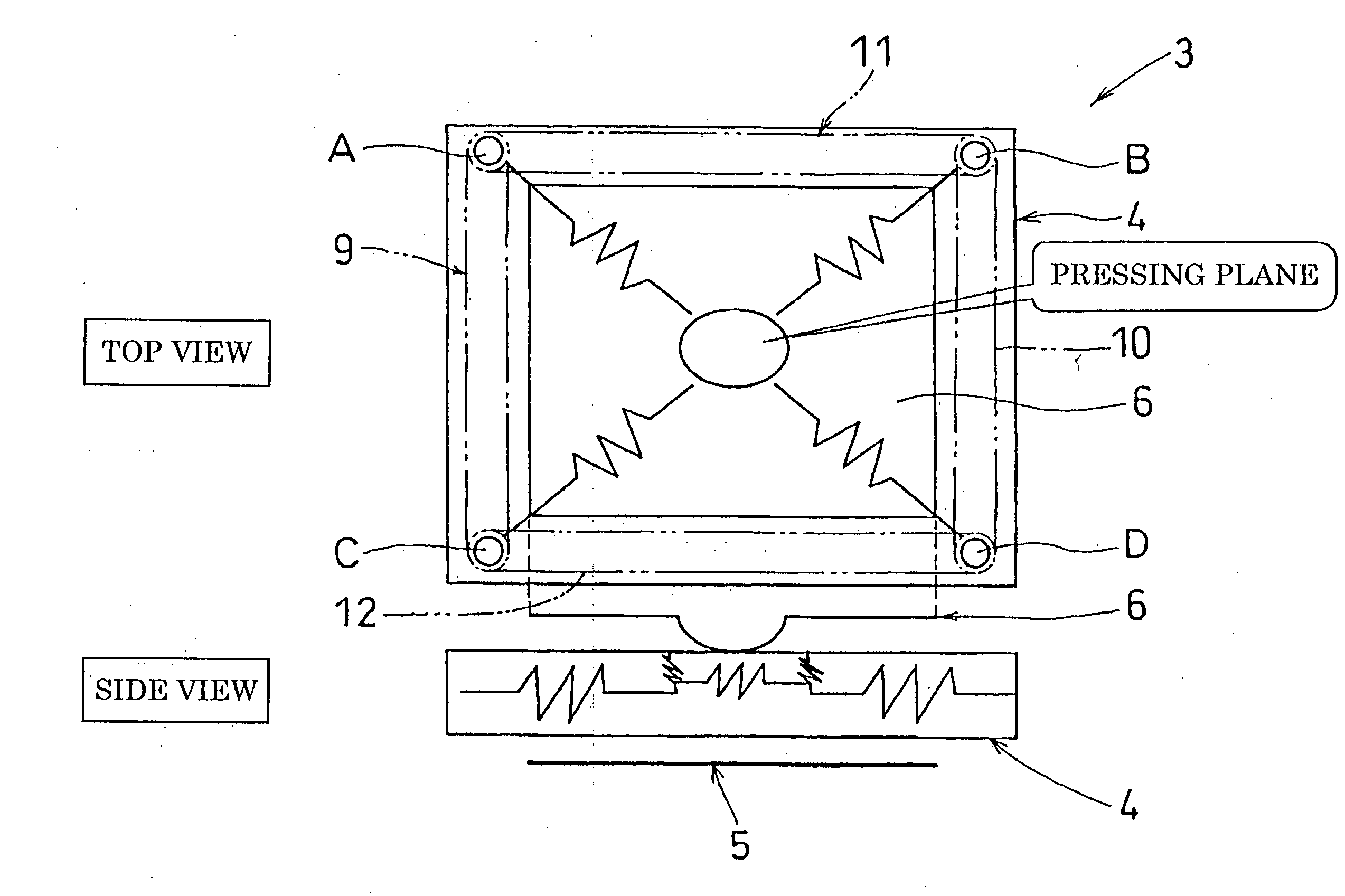
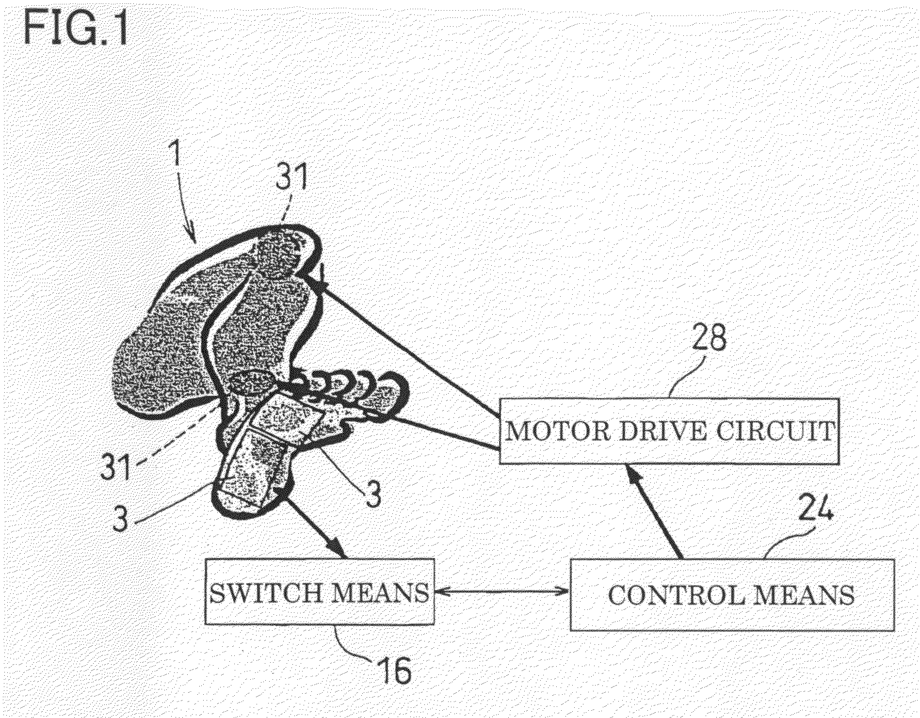
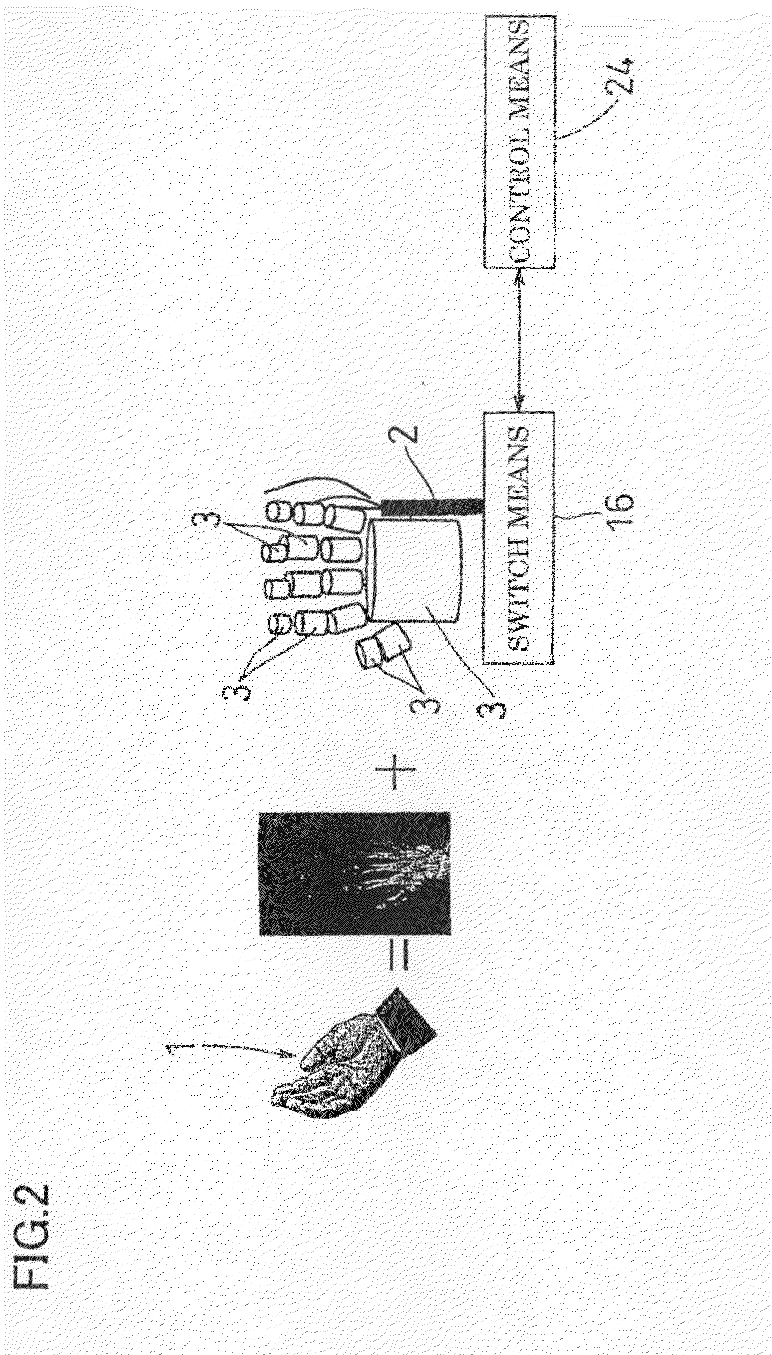
[0053]Hereafter, embodiments of the present invention will be described referring to the drawings. FIGS. 1 and 2 show one embodiment in which the present invention is applied to a palm or a hand of a robot (controlled apparatus) 1. In the embodiment, a tactile sensor 3 that is built in a unit is installed onto joints of a sole, fingers, or a palm that are skeleton of a robot 1, being fitting to these parts. In the present embodiment, as shown in FIG. 1, the two tactile sensors 3 are installed onto the sole of the robot 1, and as shown in FIG. 2, the fourteen tactile sensors 3 are installed onto the fingers of the hand and each one tactile sensor is installed onto the palm of the hand and to the back of the hand, respectively. Since these tactile sensors 3 are arranged being fitted to joints of the hand and the sole of the foot, the joints can be operated freely and magnitudes of pressures thereof and their areas and a center of gravity location of the pressure can be obtained with a...


PUM


Abstract

A tactile sensor for detecting a variation in pressing real-time. The tactile sensor is simple in structure, detects a variation in pressing by using reduced wires, has increased reliability and reduced cost, and can obtain information accurately. A sheet has, along its surface, resistors arranged in an X direction and Y direction, has a resistor in Z direction corresponding to the thickness direction of the sheet, and has a pressure sensitive resistor sheet (4) whose resistance in the Z direction varies according to pressing in the thickness direction. At least a pair of electrodes (9, 10, 11, 12) is placed in the periphery of the pressure sensitive sheet (4), and the electrodes conduct a current to at least either of the resistor in the X direction or the resistor in the Y direction. Also, at least a pair of conductors (5, 6) for conducting a current to the resistor in the Z direction is provided on the surface of the pressure sensitive sheet (4).

Description

TECHNICAL FIELD[0001]The present invention relates to detection and control of input information of pressure and its position, and relates to a tactile sensor for detecting contact coordinates, contact pressure, and contact length by a simple method and a tactile sensor application apparatus using the tactile sensor.BACKGROUND ART[0002]Almost every conventional pressure and position detection sensor detects a pressure distribution, and scans sensors or electrodes arranged on an X-Y matrix to detect the pressure distribution and calculates positions of pressure (see, for example, patent documents 1 and 2). However, in order to X-Y scan all the positions that are subjected to pressures, it takes time to calculate a center of gravity location of the pressures, an area of the pressures and an average pressure that are necessary information. For example, in the case where a sensor of 50×50 mm with a resolution of 1 mm is scanned even at 100 MHz, it takes 25 μl sec per element. Moreover, ...

Claims


Application Information

Patent Timeline
Patent Type & Authority Applications(United States)
IPC IPC(8): G06F3/045
CPCA61B5/447B25J13/084G01L5/161G01L5/228G06F3/045G01L5/162G06F3/04146G01L5/1623
Inventor MORIMOTO, KENICHI
Owner EWSYST
Why Eureka
Try Eureka