Multiple winding electric machine

a multi-winding, electric machine technology, applied in the direction of electric generator control, dynamo-electric converter control, transportation and packaging, etc., can solve the problems of increasing the number of vehicles, consuming more electrical energy than in conventional internal combustion vehicles, and requiring larger alternators for mid-to-upscale conventional vehicles

Inactive Publication Date: 2008-11-06
GM GLOBAL TECH OPERATIONS LLC
View PDF3 Cites 12 Cited by
  • Summary
  • Abstract
  • Description
  • Claims
  • Application Information

AI Technical Summary

Problems solved by technology

Increasingly, mid-to-upscale conventional (non hybrid) vehicles require larger alternators because of electrical consumption by accessories of all kinds.
In the case of hybrid vehicles, in particular, the motive electric motor(s) and accessory-drive electric motor(s) consume much more electrical energy than in conventional internal combustion vehicles.
This need for increased alternator capacity further exacerbates both the packaging issues and the vehicular mass increase issues presented by the use of additional electric motors and a larger battery pa

Method used


Image

  • Multiple winding electric machine
  • Multiple winding electric machine
  • Multiple winding electric machine

Examples


Embodiment Construction

[0013]The following detailed description is merely exemplary in nature and is not intended to limit the described embodiments or the application and uses of the described embodiments. Furthermore, there is no intention to be bound by any expressed or implied theory presented in the preceding technical field, background, brief summary or the following detailed description.

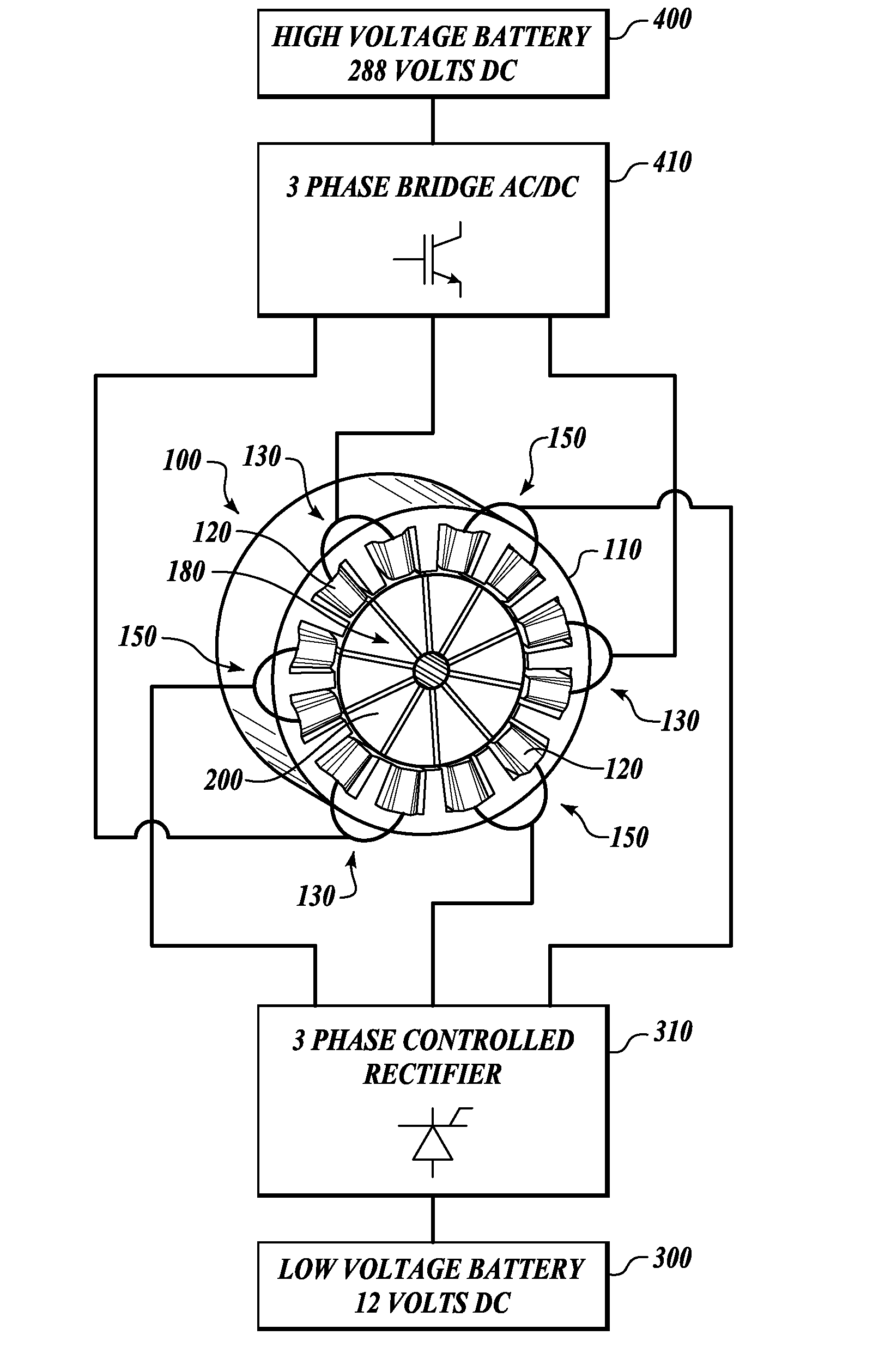
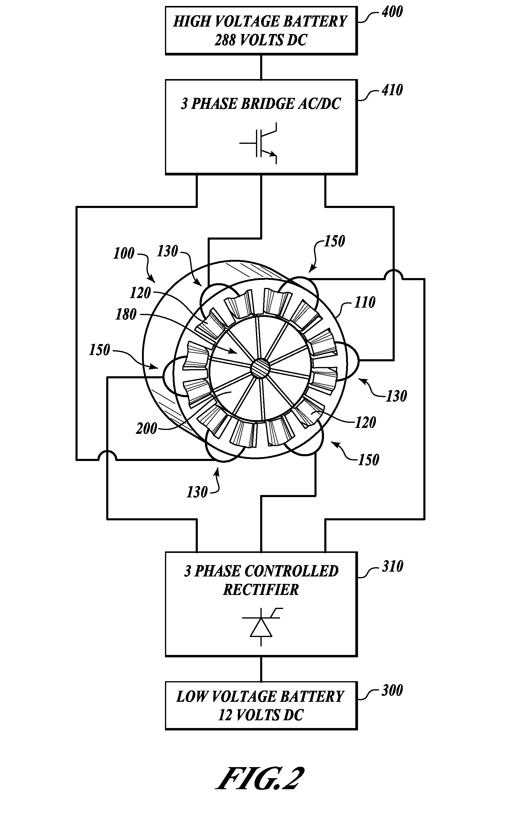
[0014]An exemplary embodiment provides a “dual coil set” electric machine that can simultaneously operate as motor and alternator, or operate as either one or the other. The electric machine includes a stator, a rotor and electrically conductive coils as major components. Existing manufacturing tools may be configured to fabricate the electric machine. The coils differ from those of conventional electric motors in that the coils are provided as “dual coil sets.”“Dual coil sets” or “dual coil groups” as used herein means that the electric motor includes two electrically and magnetically isolated sets or groups of coi...


PUM


Abstract

An exemplary embodiment provides an electrical machine apparatus that includes a rotor coupled to an armature and a stator surrounding the rotor. The stator has a series of coils; the series of coils configured into a first group of coils and a second group of coils, the first group of coils electrically and magnetically isolated from the second group of coils. The electric machine is capable of simultaneously acting as an electric motor and generating electricity as an alternator.

Description

TECHNICAL FIELD[0001]The embodiments described herein generally relate to electric machines including motors and generators, and more particularly relates to an electric machine that can simultaneously function as a motor and as a generator / alternator, or as either one or the other.BACKGROUND[0002]In principle, a typical electric motor includes a central rotor surrounded by a stator and an armature coupled to the rotor. The stator includes wires or coils through which an electrical current flows to produce a magnetic field. The magnetic field interacts with an armature that in turn applies a torque to the rotor thereby causing the rotor to rotate. An example of a simple electric motor 10 is shown in schematic form in FIG. 1. The motor 10 includes a stator 12 made up of a pair of permanent magnets 14, 16 in this example. Stators may also include a cylindrical ring containing coils that generate a magnetic field, when the coils are energized, for example. In FIG. 1, an armature 20 has...

Claims


Application Information

Patent Timeline
IPC IPC(8): B60K6/26H02K47/14H02P11/04
CPCB60K6/26B60K6/28H02K47/18H02P11/06H02P25/22
Inventor MESE, ERKAN
Owner GM GLOBAL TECH OPERATIONS LLC
Why Eureka
Try Eureka