Antenna device having a non-electrical engagement during pre-lock

a non-electrical engagement and antenna technology, applied in the direction of coupling device connection, quick-releasable antenna elements, collapsible antenna means, etc., can solve the problem of water leakage through the antenna mounting hol

Active Publication Date: 2008-11-06
FORD GLOBAL TECH LLC
View PDF9 Cites 10 Cited by
  • Summary
  • Abstract
  • Description
  • Claims
  • Application Information

AI Technical Summary

Problems solved by technology

Typically, when an antenna base is snapped onto the main body of a vehicle, the antenna base appears to be fully installed, but the bolt or nut has not been driven to provide full compression between the antenna base and the vehicle body, sealing between the antenna base and the vehicle body and grounding of the antenna to the vehicle body.
The undesired result of having the bolt or nut not driven while appearing to be fully installed is that a vehicle can be shipped to a customer with the potential for water leakage through the antenna mounting hole.

Method used


Image

  • Antenna device having a non-electrical engagement during pre-lock
  • Antenna device having a non-electrical engagement during pre-lock
  • Antenna device having a non-electrical engagement during pre-lock

Examples


first embodiment

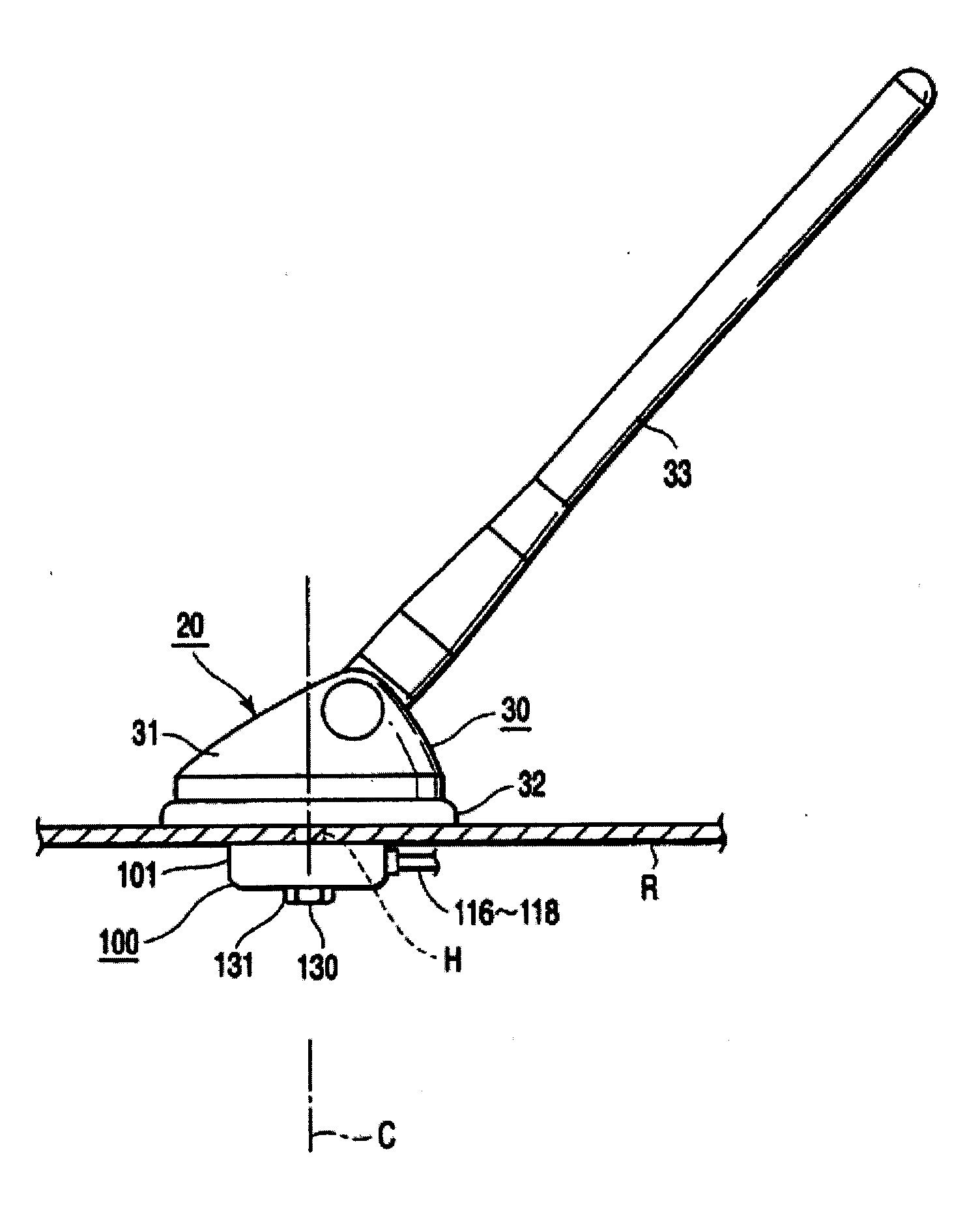
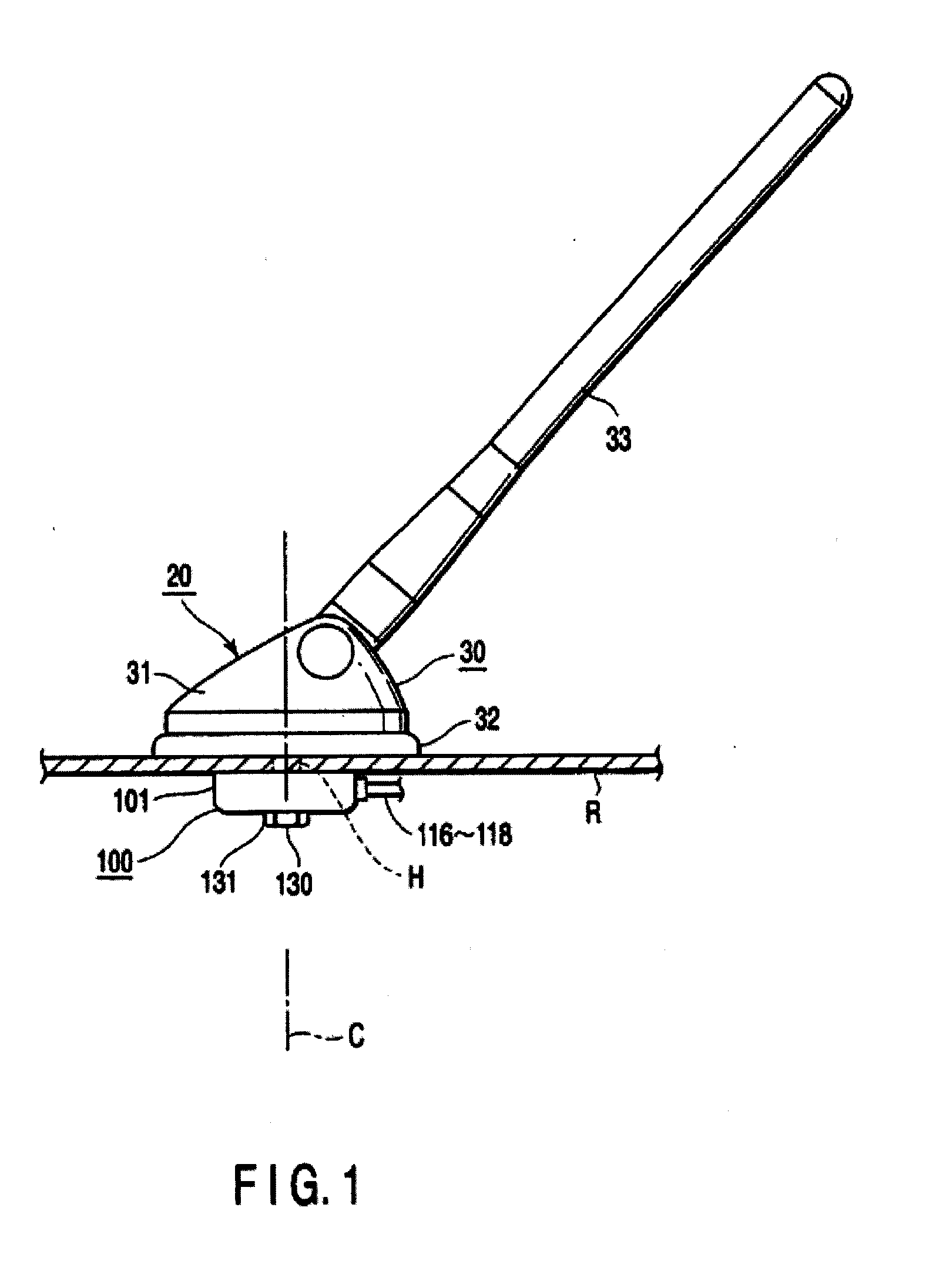
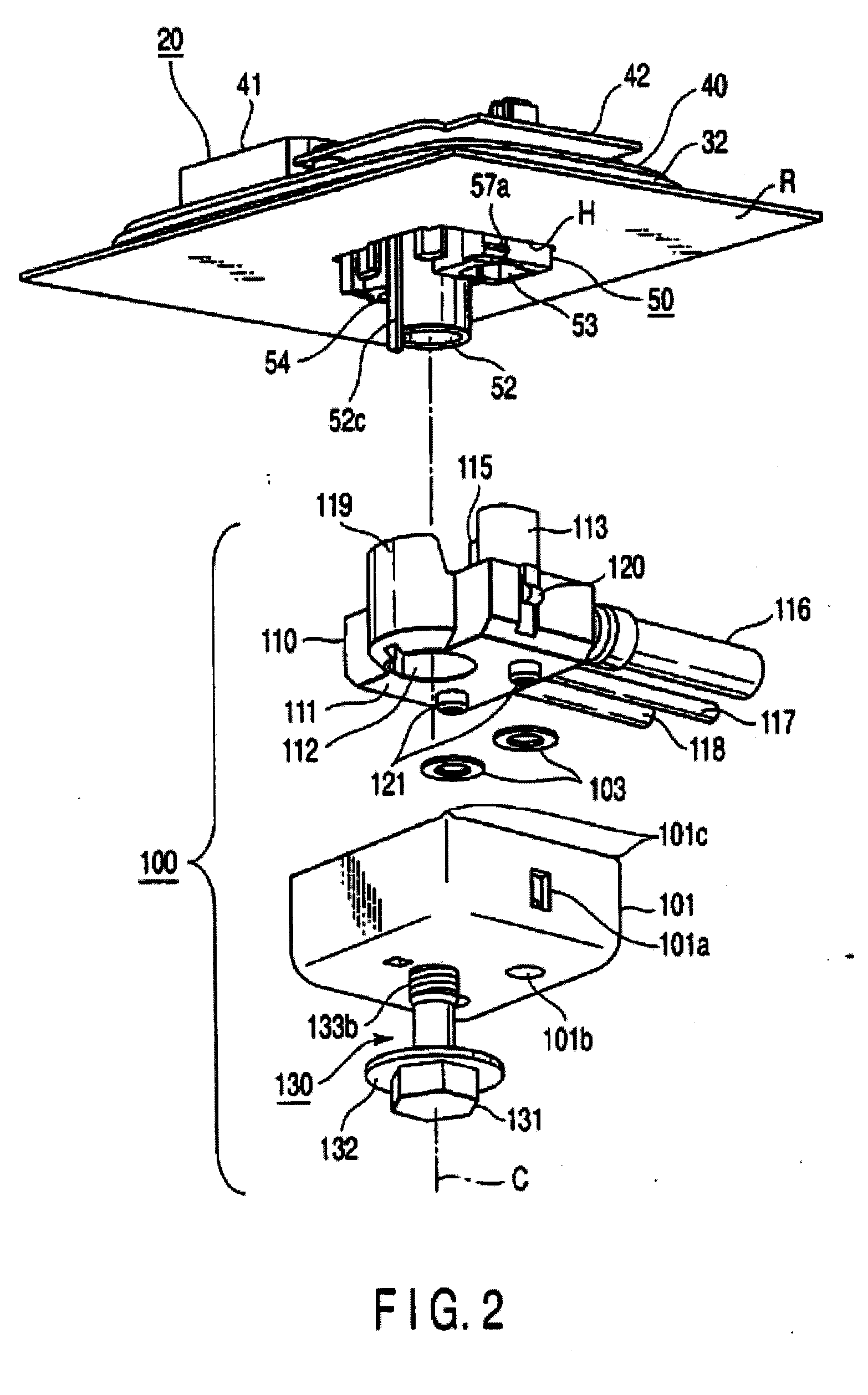
[0029]FIG. 1 is a side view showing an antenna device 20 according to the present invention; FIG. 2 is an exploded perspective view showing the antenna device 20 from the lower side; FIG. 3 is a longitudinal cross section showing the antenna device 20; FIG. 4 is a plan view showing an antenna main body 30 from a lower side when the main body is inserted into a roof panel R; FIG. 5 is a perspective view showing a fixing member 100; FIGS. 6 and 7 are perspective views showing a process of assembling the antenna main body 30; and FIGS. 8 to 10 are longitudinal section views showing a process of assembling the antenna device 20. C in these figures indicates a tightening direction in which a screw is mounted by tightening a bolt 130 described later. In addition, R in these figures indicates a roof panel which configures a vehicle body such as an automobile, and H indicates an antenna mount hole. The antenna mount hole H is formed in a substantially rectangular shape, and a cutout H1 is p...

second embodiment

[0053]FIG. 11 is a longitudinal cross section showing an antenna device 220 according to the present invention in an exploded manner; FIG. 12 is a plan view when the antenna device is seen in the direction indicated by the arrow in double dot and chain line α shown in FIG. 11; and FIG. 13 is a plan view when the antenna device is seen in the direction indicated by the arrow in double dot and chain line β shown in FIG. 11. C in these figures indicates a tightening direction in which a screw is mounted by tightening a nut 302 described later.

[0054]The antenna device 220 has an antenna main body 230 and a fixing member 300. The antenna main body 230 comprises an antenna cover 231 and an AM / FM antenna element 232 mounted on the antenna cover 231.

[0055]A base 240 is mounted at the inside of the antenna cover 231 as shown in FIG. 11. A patch antenna 241 and a substrate 242 are provided at an upper face side of the base 240. In addition, a cylinder body 243 is provided at a lower face side...


PUM


Abstract

An antenna device has an antenna main body, a fixing member and a bolt. The antenna main body comprises an antenna element, female connectors provided at a first connector, a female screw section, and an engagement claw inserted into an antenna mount hole to make engagement with a lower side face of a roof panel. A fixing member comprises cables, male connectors provided at a second connector, the male connectors being provided to make mechanical engagement with female connectors without an electrical connection, and being connected to the cable, and a male screw section helically fitted to a female screw section, thereby tightening the female connectors, the male connectors, and a roof panel with one another. A bolt may be mounted between the male and female connectors to allow electrical connection therebetween.

Description

BACKGROUND OF THE INVENTION[0001]1. Field of the Invention[0002]The multiple embodiments of present invention relate to an antenna device mounted on a vehicle body such as an automobile.[0003]2. Background Art[0004]Conventionally, a variety of antenna devices may be mounted on a vehicle body of an automobile. FIGS. 14 and 15 are views each showing an example of such an antenna device. As depicted, an antenna device 1 is composed of: an antenna main body 2 provided at an upper side of a roof panel R; and a mount nut 10 provided at a lower side of the roof panel R. The antenna main body 2 comprises: an antenna cover 3; an antenna element 4 mounted on the antenna cover 3; a pad section 5 disposed between the antenna cover 3 and the roof panel R; and a base section (not shown) and a substrate 6 provided at the pad section 5. A matching circuit or an amplifier circuit and a duplexer are incorporated in the substrate 6.[0005]A protrusion section 7 is provided on a lower face of the base s...

Claims


Application Information

Patent Timeline
Patent Type & Authority Applications(United States)
IPC IPC(8): H01Q1/32H01R13/642
CPCH01Q1/088H01Q1/3275H01R13/6215H01R2201/02H01R2201/26
Inventor TENGLER, DAVID RICHARDLI, QINGMANDUZZI, KENDRA DIANEHULING, JACK JEFFREY
Owner FORD GLOBAL TECH LLC
Why Eureka
Try Eureka