Three dimensional shape correlator

a correlator and three-dimensional technology, applied in wave based measurement systems, instruments, reradiation, etc., can solve the problems of inaccurate and untimely target recognition, and achieve the effect of high effective, accurate and efficient target recognition, and fast processing speed

Inactive Publication Date: 2008-11-06
U S OF A AS REPRESENTED BY THE SEC OF THE NAVY
View PDF1 Cites 81 Cited by
  • Summary
  • Abstract
  • Description
  • Claims
  • Application Information

AI Technical Summary

Benefits of technology

[0009]The present invention overcomes some of the difficulties of the past including those mentioned above in that it comprises a highly effective computer software program which processes three dimensional laser radar or Ladar data for fast, accurate and efficient target recognition.

Problems solved by technology

These target recognition devices generally operate in a two dimensional space resulting in target recognition which is sometimes inaccurate and also not timely in providing needed target recognition data.
The fact that only two dimensional data is used will often lead to an erroneous result which can be very costly especially to military personnel in a combat environment who depend on accurate results to formulate their battle plans and defenses against these targets or weapons systems.

Method used


Image

  • Three dimensional shape correlator
  • Three dimensional shape correlator
  • Three dimensional shape correlator

Examples


Embodiment Construction

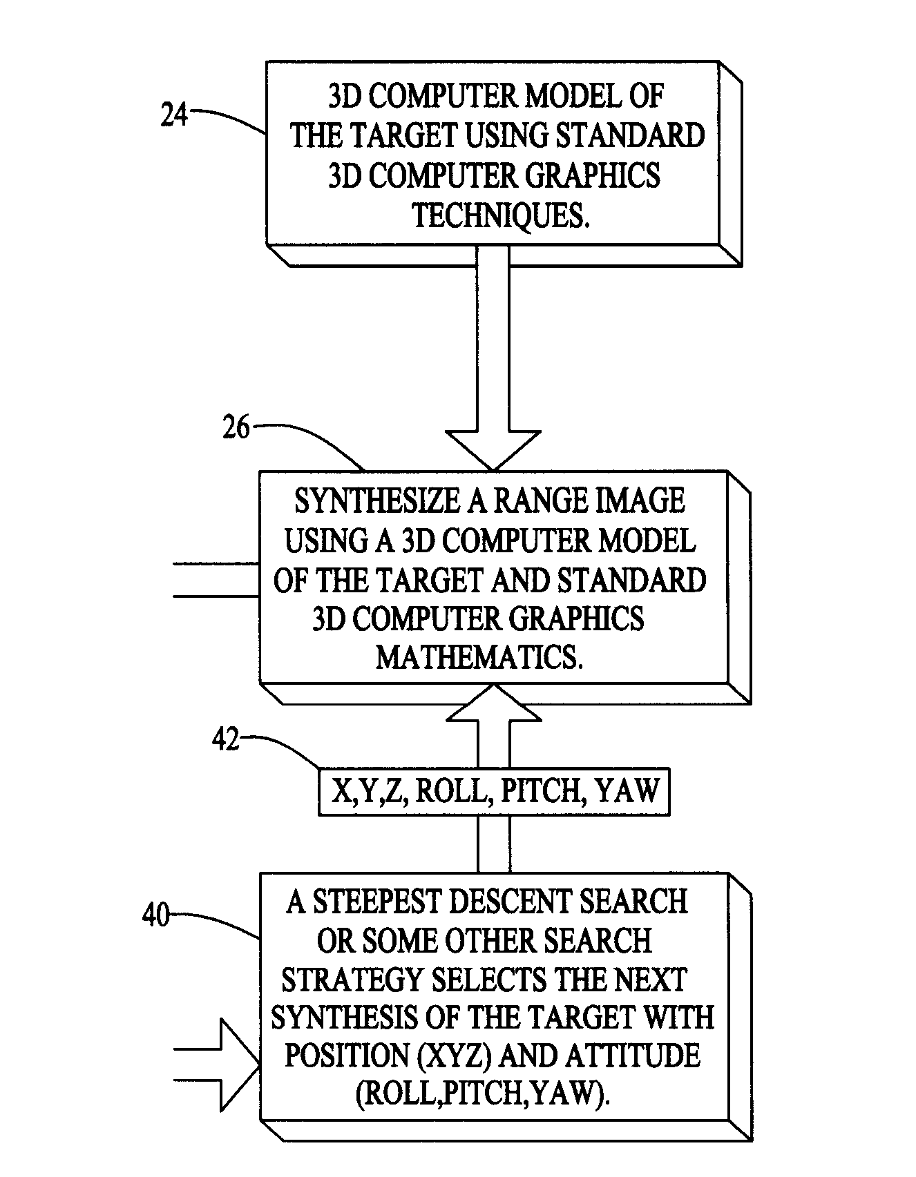
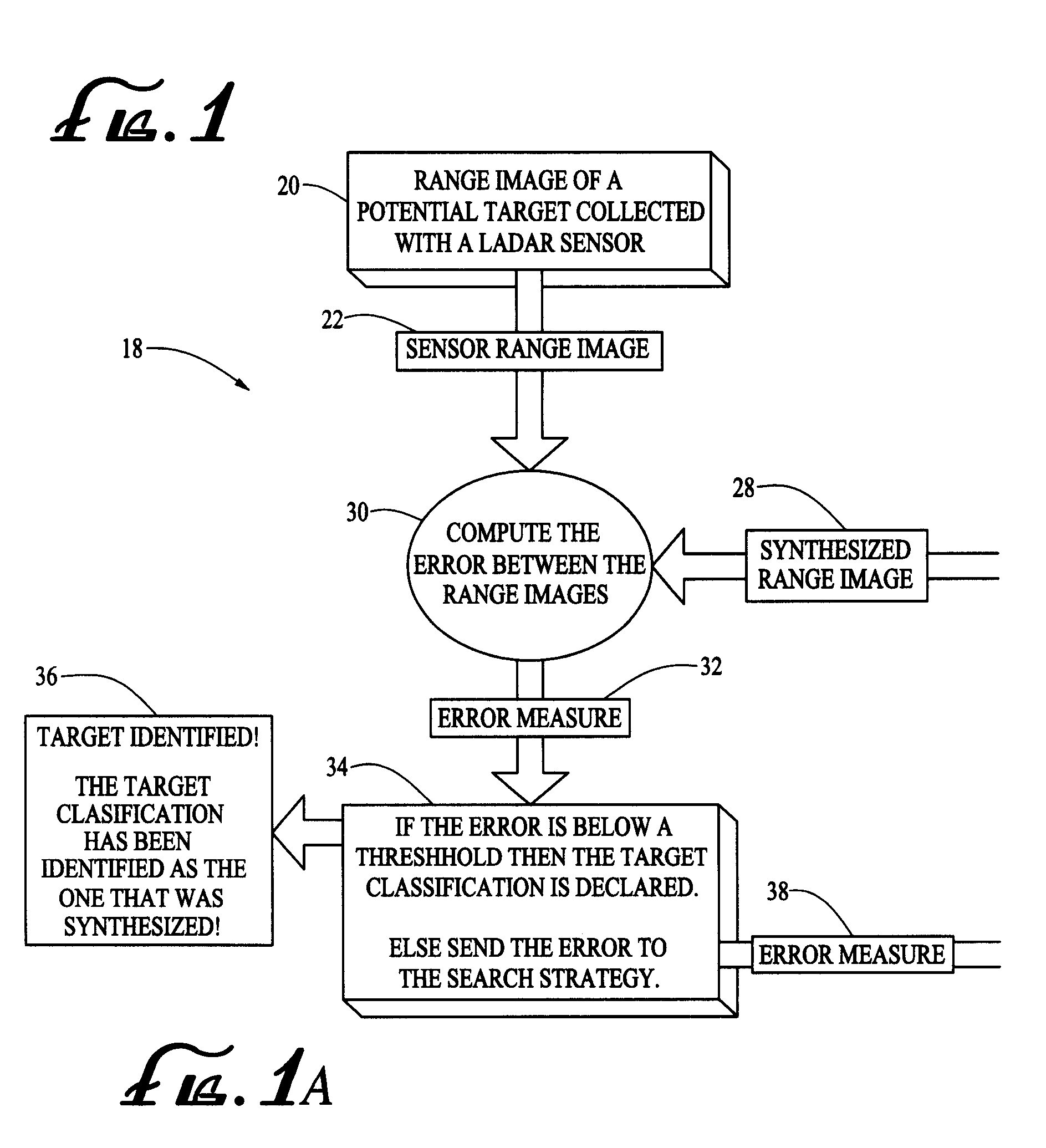
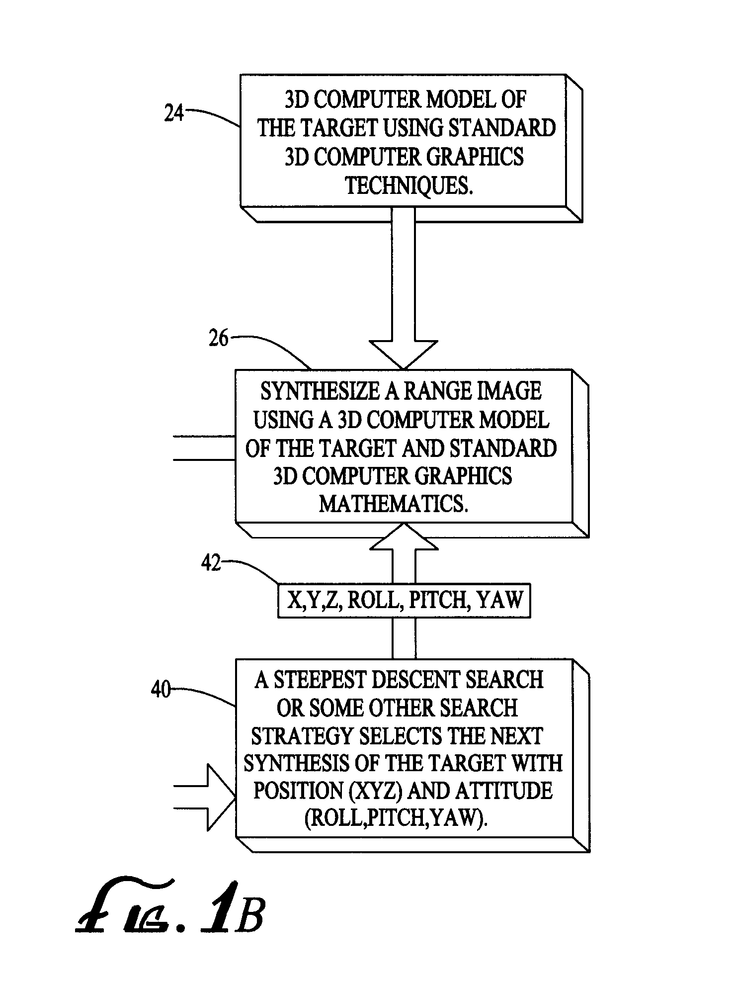
[0022]Referring to FIG. 1, a scan of Ladar data is obtained from a Ladar sensor on board an aircraft or another military vehicle. The range image of a potential target, such as a tank or military vehicle is collected from the Ladar data provided by the Ladar source (program step 20 of flow chart 18).

[0023]At this time it should be noted that LADAR (laser detection and ranging) is an optical remote sensing technology which measures scattered light to find range and / or other information about a distant target. Normally Ladar uses laser pulses to determine distance to an object or surface. Like the similar radar technology, the range to an object is determined by measuring the time delay between transmission of a pulse and detection of the reflected signal.

[0024]Next, the Sensor range image of a potential target is MACH filtered to find detection points for the target in the Ladar data (program step 22). MACH filters also referred to as maximum height correlation filters are correlatio...


PUM


Abstract

A three dimensional shape correlation computer software program which uses laser radar data for target identification. The correlation program obtains a scan of laser radar data of a target from a Ladar sensor. The data includes a plurality of X,Y,Z coordinate detection points for the target. The software simulates the sensor scan using a 3D wire-frame model of the target. An X,Y,Z coordinate location is computed for every point in the computer model of the target. The software compares the X,Y,Z coordinate detection points for the target with the X,Y,Z coordinate points for the computer model to determine if the points match. When there is a match a target identification is declared.

Description

[0001]The application is a continuation-in-part of U.S. patent application Ser. No. 11 / 787,343, filed Apr. 12, 2007.BACKGROUND OF THE INVENTION[0002]1. Field of the Invention[0003]The present invention relates generally to target recognition. More particularly, the present invention relates to an automatic target recognition (ATR) computer software program which uses Laser Radar (Ladar) data and three dimensional image data for target identification.[0004]2. Description of the Prior Art[0005]There is currently a need by the military for fast and accurate real time target recognition especially in a battle field environment. There are several benefits to having instantaneous and accurate target recognition including the prevention of serious harm or loss of life to troops in a hostile environment.[0006]In the past target recognition devices have utilized maximum average correlation height (MACH) filtering techniques. These target recognition devices generally operate in a two dimensi...

Claims


Application Information

Patent Timeline
Patent Type & Authority Applications(United States)
IPC IPC(8): G01B11/24
CPCG01S7/4802G01S17/89G06K9/00201G06K9/3241G06V20/64G06V10/255
Inventor HILDE, JEFFREY J.
Owner U S OF A AS REPRESENTED BY THE SEC OF THE NAVY
Why Eureka
Try Eureka