Single pll demodulation of pre-formatted information embedded in optical recording medium

a technology of optical recording medium and demodulation, which is applied in the field of single-pll demodulation of pre-formatted information embedded in optical recording medium, can solve the problems of increasing the size and cost of the device, increasing the number of pins of the chip, and increasing the design complexity

Inactive Publication Date: 2008-11-06
AVAGO TECH INT SALES PTE LTD
View PDF2 Cites 7 Cited by
  • Summary
  • Abstract
  • Description
  • Claims
  • Application Information

AI Technical Summary

Problems solved by technology

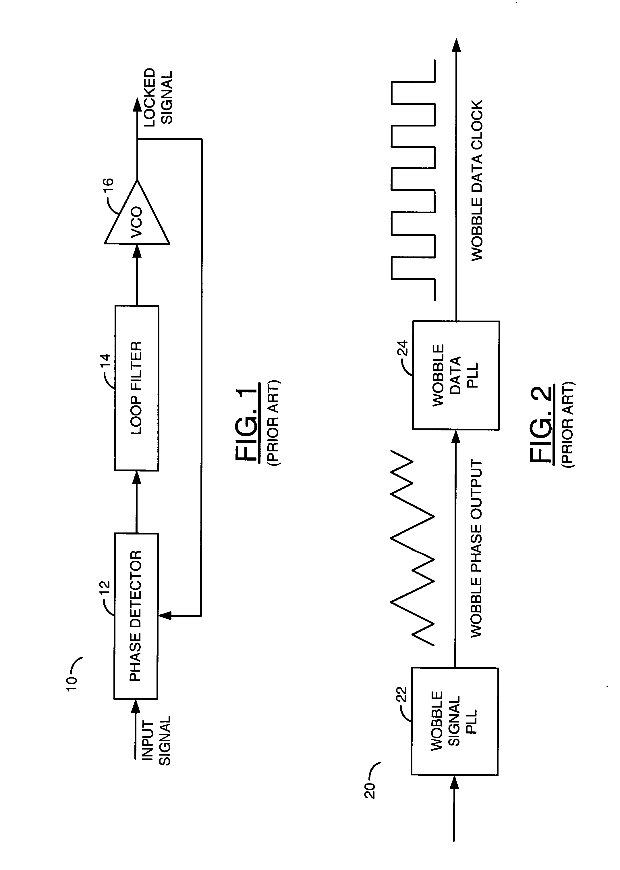
However, compared with a DVD-recordable system, the conventional two-PLL CD-recordable system has disadvantages that it requires additional circuitry for the second PLL, which increases the size and cost of the device.
In addition, the presence of multiple circuits with the same function increases the design complexity, as well as the pin count of the chip, the number of components required to support the chip, and the like.

Method used


Image

  • Single pll demodulation of pre-formatted information embedded in optical recording medium
  • Single pll demodulation of pre-formatted information embedded in optical recording medium
  • Single pll demodulation of pre-formatted information embedded in optical recording medium

Examples


Embodiment Construction

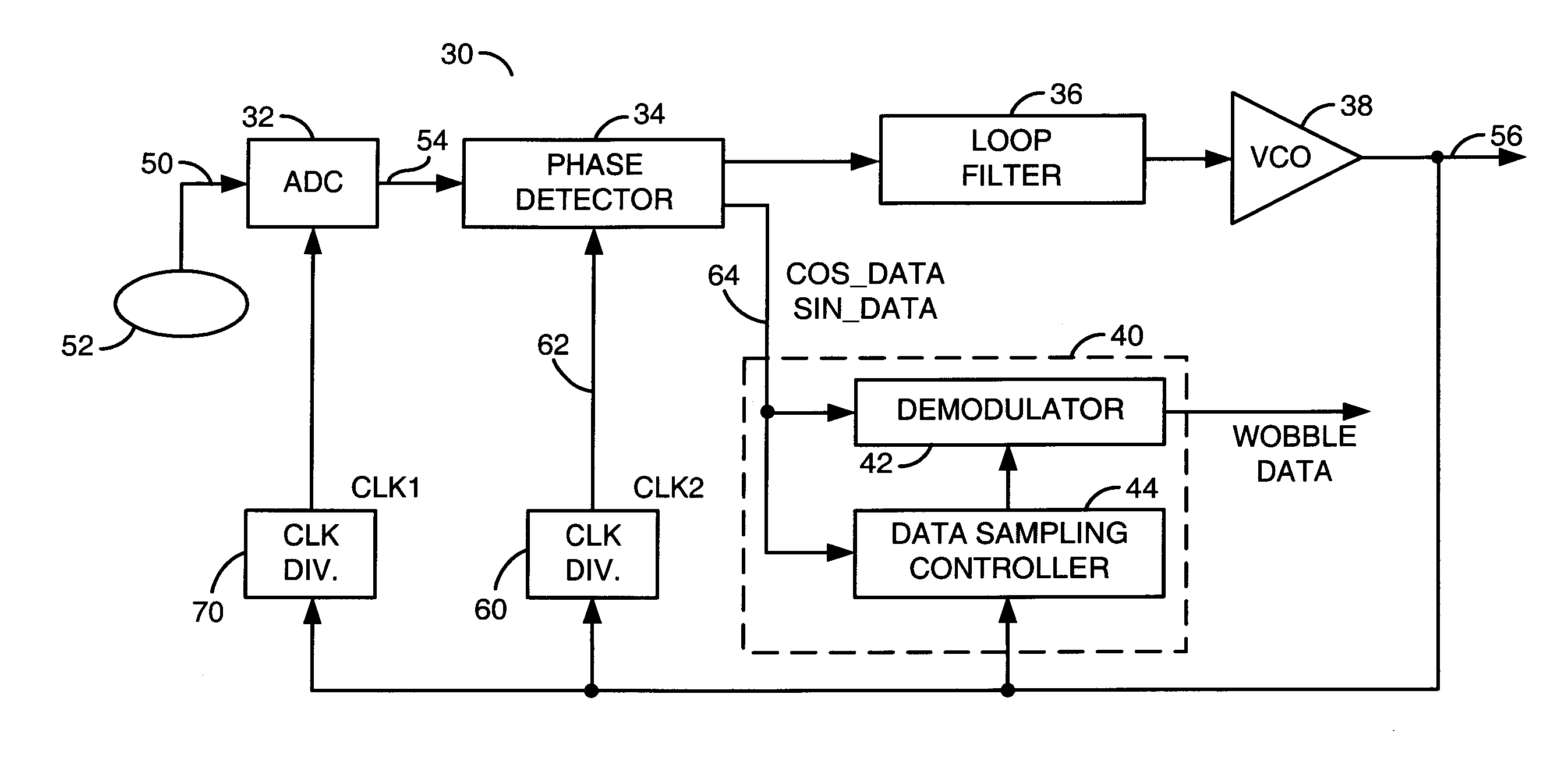
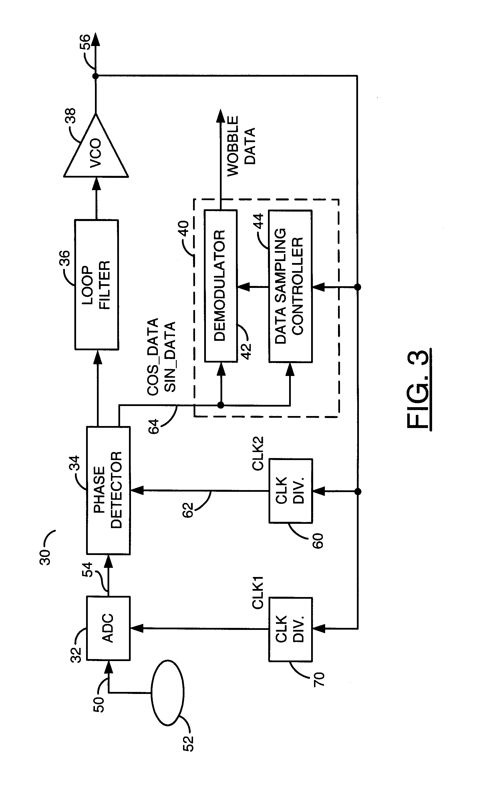
[0025]Embodiments of the present invention are described herein in the context of a single PLL demodulation of pre-formatted information embedded in an optical recording medium. Those of ordinary skill in the art will realize that the following detailed description of the present invention is illustrative only and is not intended to be in any way limiting. Other embodiments of the present invention will readily suggest themselves to such skilled persons having the benefit of this disclosure. Reference will now be made in detail to implementations of the present invention as illustrated in the accompanying drawings. The same reference indicators will be used throughout the drawings and the following detailed description to refer to the same or like parts.

[0026]In the interest of clarity, not all of the routine features of the implementations described herein are shown and described. It will, of course, be appreciated that in the development of any such actual implementation, numerous...


PUM

PropertyMeasurementUnit
phase erroraaaaaaaaaa

Abstract

A method and apparatus demodulate pre-formatted information embedded in an optical recording medium. The demodulation includes (a) receiving a wobble signal representing data symbols frequency-modulated on a carrier frequency, (b) generating a phase delta signal representing a phase difference between the wobble signal and a corresponding locked signal having the carrier frequency, (c) first sampling the phase delta signal at a data sampling interval to produce first values, (d) second sampling the phase delta signal at each halfway of the data sampling interval to generate second values, (e) determining, based on a difference between two successive second values, if the first sampling is performed at timing corresponding to an end of each data symbol, and (e) adjusting sampling timing of the first sampling towards the timing corresponding to each end of the data symbols, if the sampling timing does not corresponds to the end of each data symbol.

Description

[0001]This is a continuation of U.S. Ser. No. 11 / 012,592, filed Dec. 14, 2004, which is incorporated by reference in its entirety.FIELD OF THE INVENTION[0002]The present invention relates to optical disc systems. More particularly, the present invention relates to timing control in demodulation and writing data onto recordable optical discs.BACKGROUND OF THE INVENTION[0003]In a read-only optical recording medium, such as a compact disc (CD) read only memory (ROM) or digital versatile disc (DVD) ROM, user data is built into the disc and also provides position and timing information for reading the data. However, in a recordable CD or DVD, such position and timing information must be provided without user data. Thus, recordable CDs or DVDs are manufactured with preformatted land-groove patterns in order to encode position and timing information. Fine position information comes from the “push-pull” signal arising from the presence of the alternating land and groove patterns. Timing inf...

Claims


Application Information

Patent Timeline
Patent Type & Authority Applications(United States)
IPC IPC(8): G11B20/08
CPCG11B7/0053G11B20/10009G11B20/10222G11B20/1403
Inventor SERRANO, LOUIS J.SHIH, SHIH-MING
Owner AVAGO TECH INT SALES PTE LTD
Why Eureka
Try Eureka